FP3 MEWNET-TR
Chapter3-2. Page.43
39
3) Recommended crimp
For crimping the power supply terminals of the slave station, see “Recommended crimp” on page 36.
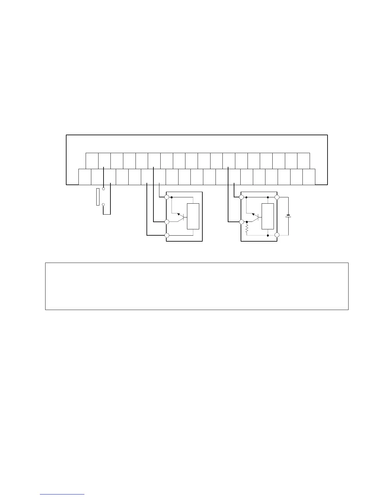
4) Wiring input
x The 24-V positive (+) terminal is connected to each positive (+) terminal, and the 24-V negative (-) terminal is
connected to each negative (-) terminal, as shown in the internal circuit diagram on page 38.
x There is no need to supply power for inputs, since they are provided with power through the internal circuit. Sensors
also use the 24 V DC supplied by the internal circuit.
Wiring example:
+
24V
-
24V
0123
+
RS
485
+
-
+
-
F.G.
-
RS
485
4567
+
-
+
-
16-input type FP I/O transmitter unit
89AB
+
-
+
-
CDEF
+
-
+
-
Internal
circuit
24 V DC
External power
supply
(See note.)
Switch
Sensor
Internal
circuit
Sensor
Notes:
x
Limit the total capacity of current used from the internal power supply to less than 1 A.
Formula:
[Internal drive current 3 mA]
×
[Number of ON points] + [Current for field devices (sensors, etc.)]
x
When supplying external power to sensors, keep it below 26.4 V DC.
x
Keep the leakage current under 1 mA when the external power is OFF.
3-2. Wiring