FP3 MEWNET-TR
Chapter6-2. Page.87
83
2) I/O link function example
Example 1:
FP1 and FP3/FP10S
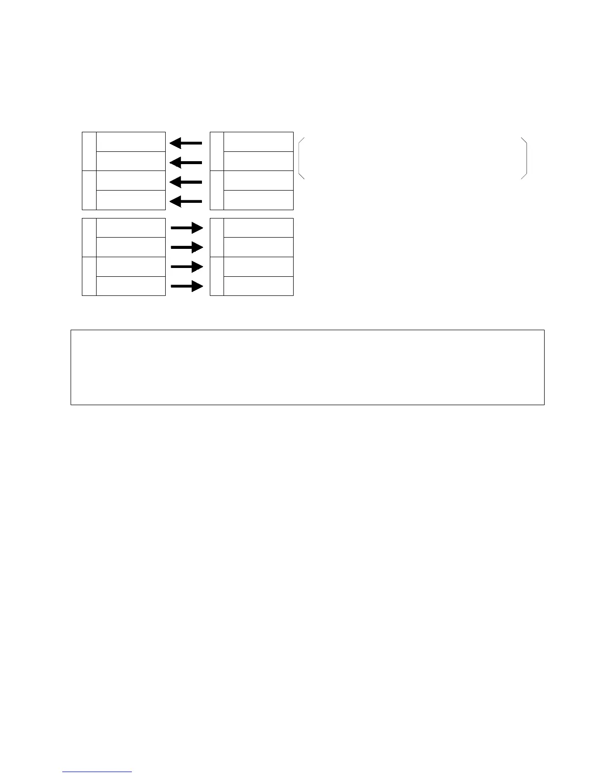
x In this example, when an output is generated from Y70 of FP1 master A, X0 of FP3/FP10S master B turns ON.
W
Y
7
Y70 to Y77
Y78 to Y7F
W
Y
8
Y80 to Y87
Y88 to Y8F
X70 to X77
X78 to X7F
W
X
8
X80 to X87
X88 to X8F
W
X
7
X0 to X7
X8 to XF
W
X
1
X10 to X17
X18 to X1F
W
X
0
W
Y
2
Y20 to Y27
Y28 to Y2F
W
Y
3
Y30 to Y37
Y38 to Y3F
FP1 Master A
(pattern No. 1)
FP3/FP10S Master B
(pattern No. 11)
Conditions of master A and B
- Installation location of master B: Slot No. 0 of the
master backplane
- I/O setting of master A and B: 32 inputs/32 outputs
Notes:
x
For the I/O allocation pattern numbers of FP1 master A, see the “FP-M/FP1 MEWNET-TR Technical
Manual.”
x
For the pattern numbers of FP3/FP10S master B, see page 64, “3. I/O Allocation Table.”
x
Whenthenumberof I/O points differs betweenmaster A and master B, I/O information cannot beexchanged
if there is no corresponding I/O point.
6-2. FP-M/FP1 Master Station and FP3/FP10S Master Station