FP3 MEWNET-TR
Chapter3-2. Page.42
38
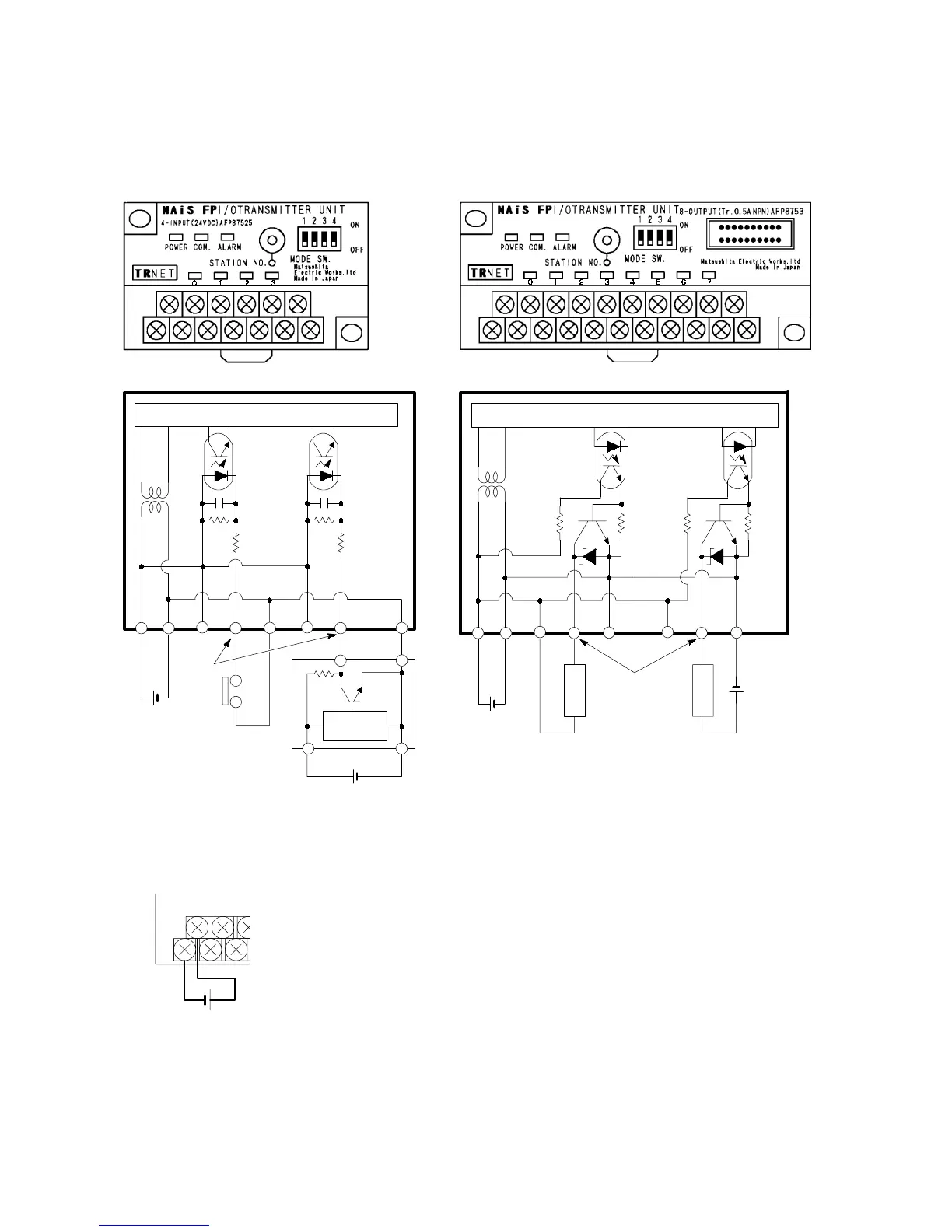
3. Wiring the I/O Terminal Power Supply of the Slave Station
1) Internal circuit diagram
Example:
FP I/O transmitter unit
Sensor
Internal circuit
24 V DC
+24 V
-
24 V
+-
Input
terminal
Optical
coupler
Load
Output typeInput type
Output typeInput type
Internal circuit
Internal
circuit
Optical
coupler
Optical
coupler
Optical
coupler
+-
24 V DC
+24 V
-
24 V
+-+-
24 V DC
Output
terminal
Load
24 V DC
2) Wiring the power supply
x The FP I/O transmitter unit must be provided directly with an external DC power supply.
x Diagram of the power supply terminal layout
24 V DC
+
-
<Power supply lines>
x The power supply to the FP I/O transmitter unit must be independent from the power supply to the master station.
x Use a twisted pair cable for the power supply line that is thicker than 2 mm
2
, or use larger conductors to minimize the
voltage drop.
3-2. Wiring