FP3 MEWNET-TR
Chapter3-1. Page.34
30
4) Installation environment
J
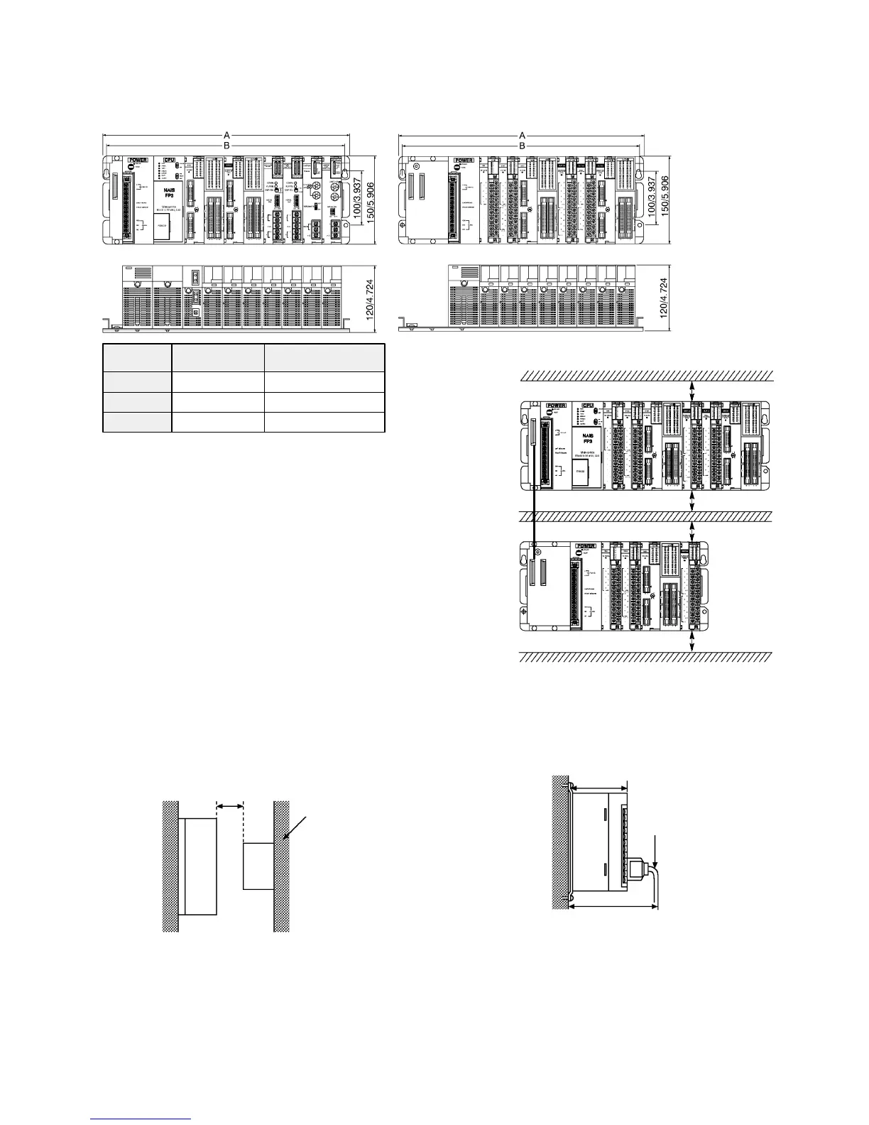
Dimensions
(unit: mm/in.)
3-slot type
5-slot type
8-slot type
260/10.236
330/12.992
435/17.126
245/9.646
315/14.402
420/16.535
A (mm/in.):
Overall length
B (mm/in.):
Mounting hole pitch
J
Installation space
x Leave at least 50 mm of space between the peripheral ducts of the
unit and other devices to allow heat radiation and unit replacement.
x Leave some further space, as indicated below, around the lower
section when using a link unit.
When using the MEWNET-P link unit: 80 mm or more
When using the ET-LAN unit: 100 mm or more
See the “FP3/FP10S HARDWARE Technical Manual” for details
about link system.
FP3/FP10S
Other
devices
100 mm/3.937 in. or more
Panel door, etc
x When installing devices facing the FP3/FP10S
such as on the door of the panel, leave a space
of at least 100 mm between that devices and the
unit to avoid the effects of heat or radiated noise.
120 mm/4.724 in.
Approx. 190 mm/7.480 in.
FP peripheral cable
x Although the depth of the unit is 120 mm, leave
a space of at least 200 mm from the mounting
surface for tool connections and wiring.
3-1. Installation
50 mm or more
50 mm or more
50 mm or more
50 mm or more
Duct or oother devices