FP3 MEWNET-TR
Chapter4-1. Page.60
56
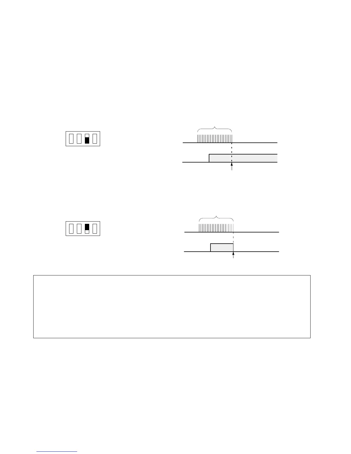
3) Output condition when a communication error occurs
x Operation mode selector No. 3 of the FP I/O transmitter unit lets you select whether to hold or turn OFF the output
of the slave station that has generated a communication error.
x Communication errors can be generated due to the following causes.
- When the transmission cable disconnects.
- When a communication error is generated with operation mode selector No. 2 of the FP3 transmitter master unit
set to OFF.
J
To hold the output of the slave station with a communication error
x Set the operation mode selector No. 3 to the ON position.
COM.LED
of slave
station
Output
(Y70)
OFF
ON
1234
MODE SW.
ON
ON
OFF
ON
OFF
Flashing (in approx. 0.2 s intervals)
Communication error occurs.
Example:
Operation mode selector of
FP I/O transmitter unit
J
To turn OFF the output of the slave station with a communication error
x Set the operation mode selector No. 3 to the OFF position.
COM.LED
of slave
station
Output
(Y70)
OFF
ON
1234
MODE SW.
OFF
ON
OFF
ON
OFF
Flashing (in approx. 0.2 s intervals)
Communication error occurs.
Example:
Operation mode selector of
FP I/O transmitter unit
Notes:
x
The output of a slave station to which power is not supplied cannot be held.
x
The output hold/OFF setting can also be made with output type expansion FP I/O terminal units using the
FP I/O transmitter unit.
Example:
When an FP I/O transmitter unit is connected with an output type expansion FP I/O terminal
unit, use the FP I/O transmitter unit to set the output operation condition (output hold/OFF
setting) of the expansion FP I/O terminal unit.
x
Please note that all of the outputs become OFF in the event of a communications error when system register
21 is set to K0 (stop), even if operation mode selector No. 2 of the FP3 transmitter master unit is set to ON
(continue).
4-1. Operation Mode Setting