FP3 MEWNET-TR
Chapter2-2. Page.17
13
2-2. Master Station
1. FP3 Transmitter Master Unit
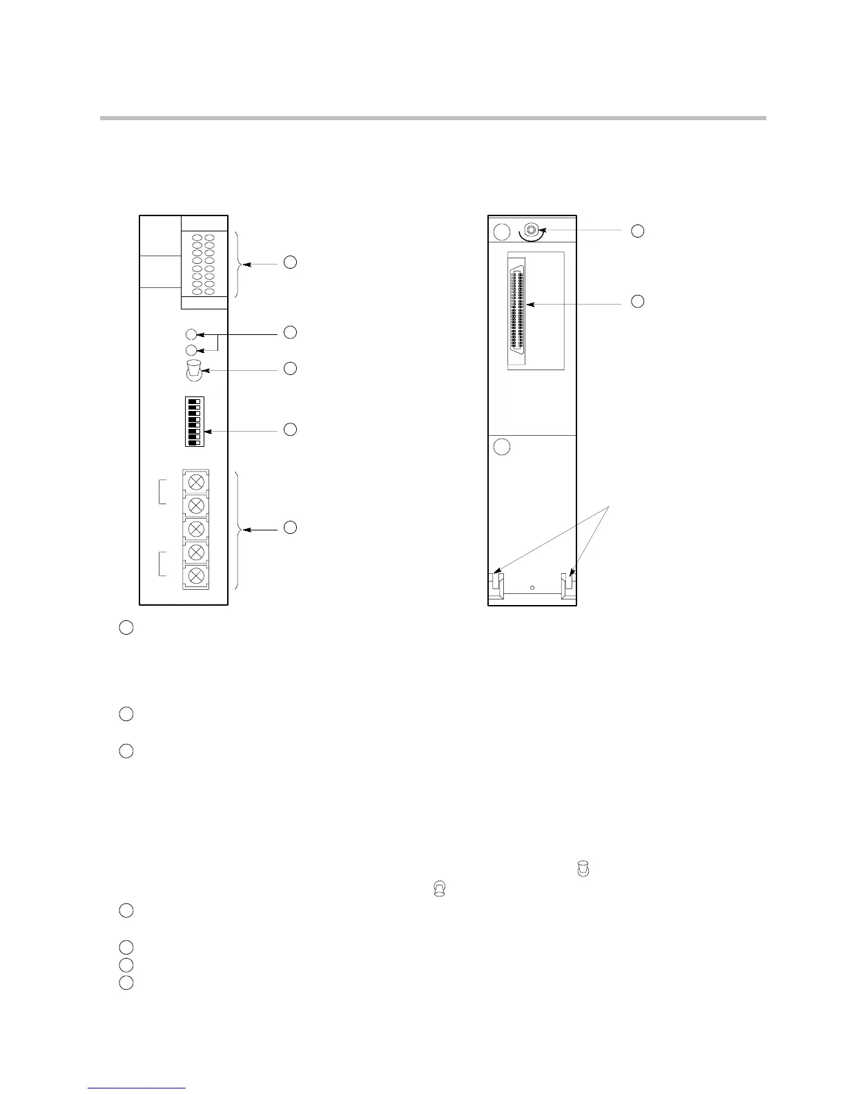
1) Parts terminology
Unit tabs
2
Operation monitor LEDs
1
Station monitor LEDs
3
Selector for station
monitor LEDs
5
RS485 interface
7
Connector
OFFON
1
2
3
4
5
6
7
8
4
Operation mode selector
6
Mounting screw
<Front> <Rear>
MASTER
0
1
2
3
4
5
6
7
8
9
A
B
C
D
E
F
TRANSMITTER
MASTER
COM.
ALARM
DSP SW.
+
-
F.G.
I
+
-
II
INPUT
OUTPUT
↕
SLAVE UNIT NO
MODE
SW.
1
Station monitor LEDs:
LEDs that monitor the slave stations (station number 0 to F) connected to
the FP3 transmitter master unit.
-When ON: Connected to a slave station
-When flashing: A communication error at this slave station number
-When OFF: Not connected to a slave station
2
Operation monitor LEDs:
Indicate the operation and communication status of the MEWNET-TR
system. See following page.
3
Selector for station monitor LEDs:
Selects the unit type (input or output) of station monitor LEDs.
Input position (INPUT): Status of slave station (FP I/O transmitter
unit) input type is indicated by station
monitor LEDs.
Output position (OUTPUT): Status of slave station (FP I/O transmitter
unit) output type is indicated by station
monitor LEDs.
The selector’s upper state is “INPUT (
)” and the lower state is
“OUTPUT (
).”
4
Operation mode selector:
Selects the MEWNET-TR communication conditions and sets the I/O
addresses. See following page.
5
RS485 interface:
Interface for MEWNET-TR communications.
6
Mounting screw:
A screw for attaching the unit to a master or expansion backplane.
7
Connector:
Connects to the slot on the master or expansion backplane.
2-2. Master Station