90
11.4. Connector Explanation
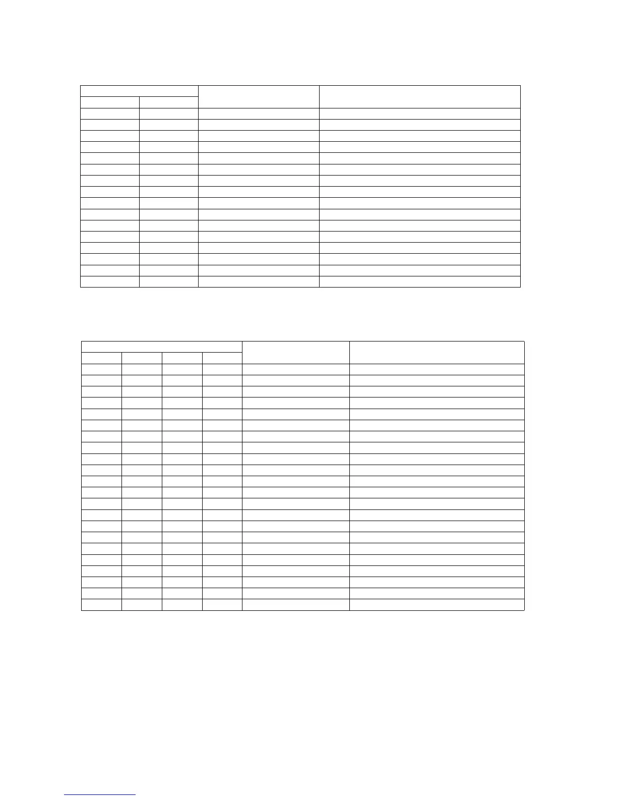
CN1001 [CONTROL Board] - CN2001 [CCD Board (F)]
Pin No. Signal Name Description
CN1001 CN2001
1 1 12VF +12 V
2 2 GND Ground
3 3 FCCD_R Front CCD Red data (Analog)
4 4 GND Ground (Shield)
5 5 FCCD_G Front CCD Green data (Analog)
6 6 GND Ground (Shield)
7 7 FCCD_B Front CCD Blue data (Analog)
8 8 GND Ground (Shield)
9 9 FCCD_TG Front CCD Transfer Gate Pulse
10 10 GND Ground (Shield)
11 11 FCCD_CLK1 Front CCD Clock
12 12 GND Ground (Shield)
13 13 FCCD_RS Front CCD Reset Pulse
14 14 GND Ground (Shield)
15 15 FCCD_CP Front CCD Clamp Pulse
16 16 GND Ground (Shield)
CN1002[CONTROL Board]/CN2501[CCD Board (B)]/
CN5003 [PAPER SENSOR Board]/ CN5004 [DOOR DETECTION Board]
Pin No. Signal Name Description
CN1002 CN2501 CN5003 CN5004
1 1 - - 12VB +12 V
2 2 - - GND Ground
3 3 - - BCCD_R Back CCD Red Data (Analog)
4 4 - - GND Ground (Shield)
5 5 - - BCCD_G Back CCD Green Data (Analog)
6 6 - - GND Ground (Shield)
7 7 - - BCCD_B Back CCD Blue Data (Analog)
8 8 - - GND Ground (Shield)
9 9 - - BCCD_TG Back CCD Transfer Gate Pulse
10 10 - - GND Ground (Shield)
11 11 - - BCCD_CLK1 Back CCD Clock
12 12 - - GND Ground (Shield)
13 13 - - BCCD_RS Back CCD Reset Pulse
14 14 - - GND Ground (Shield)
15 15 - - BCCD_CP Back CCD Clamp Pulse
16 16 - - GND Ground (Shield)
17 - 1 - GND Ground
18 - 2 - PAPER Paper Sensor
19 - 3 - +3.3V +3.3 V
20 - - 1 GND Ground
21 - - 2 DOOR Door detection
22 - - 3 +3.3V +3.3 V
 Loading...