Do you have a question about the Panasonic SA-AKX10PH and is the answer not in the manual?
| Type | Mini Hi-Fi System |
|---|---|
| FM Tuner | Yes |
| Weight | Main Unit: 2.8 kg, Speaker Box: 3.3 kg |
| Number of Discs | 1 |
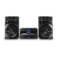
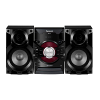
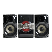
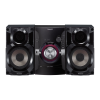
| Speaker Configuration | 2.0 |
| Output Power | 1000 W |
| Speaker Type | 2-Way |
| Connectivity | Bluetooth |
| Playable Media | CD |
| Power Output | 1000 W |
General safety guidelines for servicing electronic equipment.
Instructions for voltage selector usage on PH models before operating.
Cautions and specifications for replacing fuses in the unit.
Precautions and procedures before performing repairs or adjustments.
Explanation of the protection circuitry and how it functions.
Lists safety-critical components marked with a symbol.
Techniques to prevent damage to sensitive electronic components from static discharge.
Safety precautions regarding the laser diode in the CD pickup unit.
Cautions related to legal restrictions, specifically lead-free solder.
Specific handling precautions for the CD traverse unit, especially the laser diode.
Information on how to navigate the service manual and order parts.
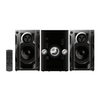
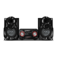
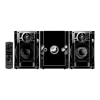
Description of buttons and their functions on the main audio unit.
Description of buttons and their functions on the remote control.
Information regarding supported media formats like CD and USB.
Procedure to perform a cold start or initialize the unit to shipping mode.
Table detailing various diagnostic modes and their operations.
Process flow charts for reliability testing of the CD mechanism.
Procedure to enter and operate the self-diagnostic mode.
Table listing error codes and their diagnosis contents for self-diagnostics.
Checking procedures for specific error codes F61 and F76 related to SMPS, D-Amp, and Main PCB.
Visual identification of key components on various PCBs for troubleshooting.
Details on the operation and control pins of the D-Amp IC.
List of service tools and equipment required for repair procedures.
Flow chart illustrating the sequence of disassembly steps for major components.
Diagrams showing the physical locations of major components and PCBs within the unit.
Step-by-step instructions for removing the top cabinet of the unit.
Instructions for disassembling the Tuner Printed Circuit Board.
Instructions for disassembling the front panel assembly.
Instructions for disassembling the Panel Printed Circuit Board.
Instructions for disassembling the Remote Sensor Printed Circuit Board.
Instructions for disassembling the CD Open Button Printed Circuit Board.
Instructions for disassembling the USB Printed Circuit Board.
Instructions for disassembling the CD lid.
Instructions for disassembling the Main Printed Circuit Board.
Detailed steps for replacing the Regulator IC (IC2701).
Instructions for disassembling the D-Amp Printed Circuit Board.
Detailed steps for replacing the Audio Digital Amp IC (IC5900).
Instructions for disassembling the SMPS (Switched-Mode Power Supply) Printed Circuit Board.
Detailed steps for replacing the Switching Regulator IC (IC5701).
Detailed steps for replacing the Rectifier Diode (D5702).
Detailed steps for replacing the Regulator Diode (D5801).
Detailed steps for replacing the Regulator Diode (D5802).
Detailed steps for replacing the Regulator Diode (D5803).
Instructions for disassembling the CD Mechanism Unit (DLS6C).
Instructions for disassembling the rear panel of the unit.
Instructions for disassembling the Voltage Selector PCB for PH models.
Instructions for disassembling the CD Servo Printed Circuit Board.
Step-by-step instructions for disassembling the traverse unit.
Step-by-step instructions for assembling the traverse unit.
Procedures for checking and repairing the Main PCB.
Procedures for checking and repairing the D-Amp PCB.
Procedures for checking and repairing the Panel PCB.
Procedures for checking and repairing the USB PCB.
Procedures for checking and repairing the SMPS PCB.
Voltage values for various pins on the CD Servo PCB in different modes.
Voltage values for various pins on the Main PCB in different modes.
Voltage values for various pins on the Main PCB in different modes.
Voltage values for various pins on the Panel PCB in different modes.
Voltage values for various pins on the USB PCB in different modes.
Voltage values for various pins on the D-Amp PCB in different modes.
Voltage values for various pins on the SMPS PCB in different modes.
Voltage values for various pins on the Tuner PCB in different modes.
Visual representations of waveforms at various test points for troubleshooting.
High-level block diagram showing the main functional units and their interconnections.
Detailed block diagram of the D-Amp section, showing power and signal flow.
Block diagram illustrating the servo and system control functions and interconnections.
Block diagram detailing the audio signal path and processing.
Block diagram of the power amplifier section, showing signal flow and components.
Block diagram of the power supply system, illustrating voltage generation and distribution.
Schematic diagram for the CD servo control circuit.
Schematic diagram for the main circuit board.
Schematic diagram for the panel circuit, including controls and display.
Schematic diagrams for CD open button, remote sensor, and tuner circuits.
Schematic diagram for the USB interface circuit.
Schematic diagram for the D-Amp (Digital Amplifier) circuit.
Schematic diagram for the SMPS (Switched-Mode Power Supply) circuit.
Schematic diagram for the voltage selector circuit, specific to PH models.
Layout diagrams for CD Servo, Tuner, and Voltage Selector PCBs.
Layout diagram for the Main Printed Circuit Board.
Layout diagram for the Panel Printed Circuit Board.
Layout diagrams for CD Open Button, Remote Sensor, USB, and D-Amp PCBs.
Layout diagram for the SMPS PCB, specific to PH models.
Layout diagram for the SMPS PCB, specific to PN models.
Pin terminal functions for the Micro-Processor IC (IC2801).
Pin terminal functions for the FL Driver IC (IC6901).
Exploded view of the unit with mechanical parts identified.
Identification of cabinet parts in the exploded view.
Diagram illustrating the packaging of the unit and accessories.
Detailed list of mechanical replacement parts with their part numbers.
Detailed list of electrical replacement parts, including PCBs, ICs, transistors, and diodes.