DOC-0017-03-EN: AC15 Series - Hardware Installation Manual
116 (125) DOC-0017-03-EN-B 04.04.2023
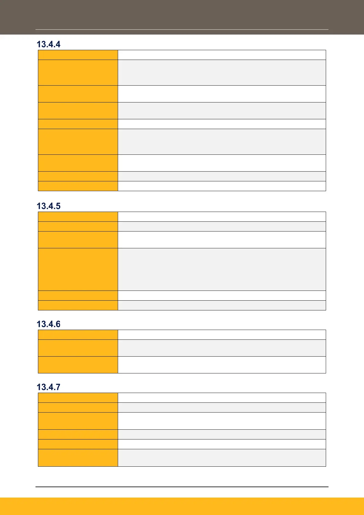
High Speed Digital Inputs
DI4, DI5, referenced to 0V
Input Voltage Range:
- Low state <0.8V
- High state >4.2V
Typical Rising
2.9V
Typical Falling
2.2V
Counting Modes:
Clock & Direction
Clock
Maximum Count
100kHz
Digital Outputs
Terminal Idents:
DX1, DX2, referenced to 0V
Nominal Output Voltage:
Minimum Output
18V @ 50mA
Maximum Output
Current:
- 50mA (Each output, or Total outputs & User +24V output
combined)
Frames 2 – 5:
- 50mA (Each output, or Total outputs combined)
Isolated:
Short Circuit Protection:
Relay Outputs
Terminal Idents:
Maximum Contact
230Vac (Overvoltage Category II, TN) / 30Vdc
Current:
2Arms
Motor Thermistor Input
Terminal Idents:
Compatible Thermistors:
Trip Threshold:
Rising resistance: 2500Ω to 2800Ω
Falling resistance: 1000Ω to 1200Ω
Response Time:
Thermistor Self Heating:
<15mW @ rising resistance threshold
Isolated:
No – thermistor wiring requires double or reinforced insulation to live
voltages

 Loading...


