DOC-0017-03-EN: AC15 Series - Hardware Installation Manual
DOC-0017-03-EN-B 04.04.2023 49 (125)
EMC
In addition to the mandatory requirements of EN61800-3, the STO functionality has been subjected to
testing for immunity at higher levels. In particular, the STO function (only) has been tested for radiated
immunity according to EN61800-5-2:2017 Annex E up to 6GHz which includes frequencies used by mobile
transmitters in general.
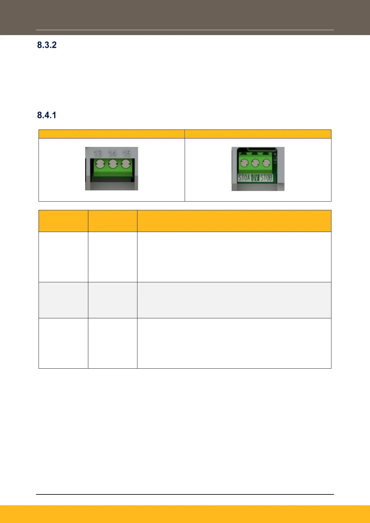
8.4 STO Operation
Terminal Identifications
Frame 1
13 STOA
- 0V or not connected, STO is ‘Active’ on channel A. Drive
will not run.
- 24V, STO is ‘Disabled’ on channel A. Drive will run,
providing 24V is present on STO input channel B too.
- Input is optically isolated from all other inverter terminals
14 0V
- Signal return for STO input channel A and STO input
channel B.
- This terminal must be connected to earth at one common
point in the drive system.
15 STOB
- 0V or not connected, STO is ‘Active’ on channel B. Drive
will not run.
- 24V, STO is ‘Disabled’ on channel B. Drive will run,
providing 24V is present on STO input channel A too.
- Input is optically isolated from all other inverter terminals
 Loading...


