EasyManua.ls Logo

Parker AC15 Series - Control Board Ratings

Parker AC15 Series
125 pages
To Next Page IconTo Next Page
To Previous Page IconTo Previous Page
Loading...
DOC-0017-03-EN: AC15 Series - Hardware Installation Manual
114 (125) DOC-0017-03-EN-B 04.04.2023
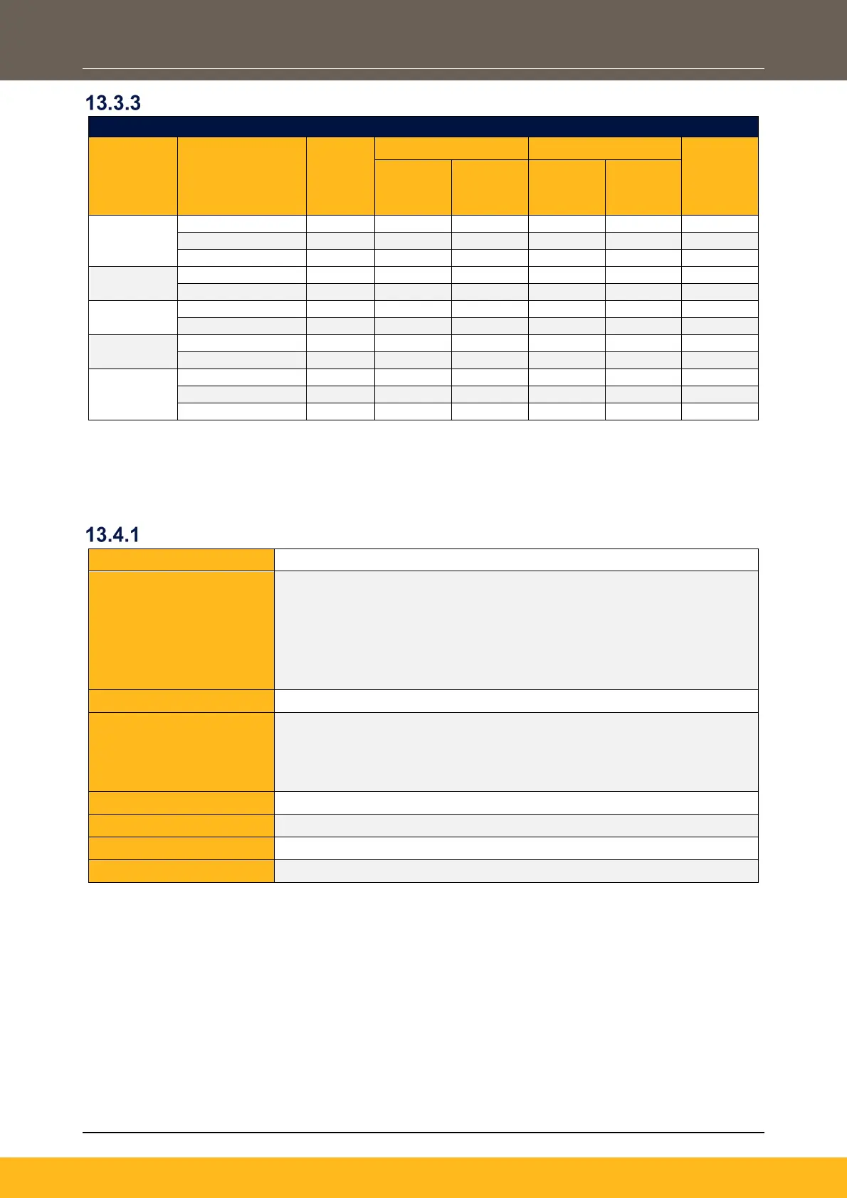
3ø, 400V Products
Frame
Size
Product Code
Motor
Power
(kW)
Continuous
Peak (Instant)
Min
Resistor
Value
(Ω)
Brake
Current
(A)
Power
Diss
(kW)
Brake
Current
(A)
Power
Diss
(kW)
1
15G-41-0012…
0.37
0.5
0.37
5.3
4.0
145
15G-41-0020...
0.75
1.0
0.75
5.3
4.0
145
15G-41-0040...
1.5
2.0
1.5
8.0
6.1
95
2
15G-42-0065...
2.2
2.9
2.2
8.5
6.5
90
15G-42-0090...
4
5.2
4.0
8.5
6.5
90
3
15G-43-0120...
5.5
7.2
5.5
8.5
6.5
90
15G-43-0170...
7.5
8.5
6.4
8.5
6.5
90
4
15G-44-0230...
11
14.4
11.0
15.3
11.7
50
15G-44-0320...
15
19.6
15.0
25.5
19.5
30
5
15G-45-0380...
18.5
24.2
18.5
25.5
19.5
30
15G-45-0440...
22
25.5
19.5
25.5
19.5
30
15G-45-0600...
30
30.6
23.3
30.6
23.3
25
Note: Peak (Instant) = Maximum 20sec, 30% ‘on’ duty (except where this value is the same as the
continuous rating)
13.4 Control Board Ratings
Analogue Inputs
Terminal Idents:
AI1, AI2, referenced to 0V
Type:
Voltage Modes:
- ± 10V (Frames 2 5 only)
- 0 10V
Current Modes:
- 0 20mA
- 4 20mA (with wire break detection)
Maximum Input Voltage:
± 30V
Input Impedance:
Voltage Mode:
- Frame 1: 18
- Frames 2 5: 10kΩ
Current Mode: <5.5V drop @ 20mA
Resolution:
12 Bit
Isolated:
No
Overcurrent Protection:
Yes (Current Mode only)
Sample / Update Rate:
1msec

Table of Contents

Related product manuals