DOC-0017-03-EN: AC15 Series - Hardware Installation Manual
28 (125) DOC-0017-03-EN-B 04.04.2023
Control Board Wiring
RISK OF ELECTRIC SHOCK
Terminal covers, main covers, and cover fixings must remain in place
while the drive is energised.
These should only ever be removed once the supply to the unit and/or
system has been disconnected, and the residual energy in the DC link
capacitors has been discharged.
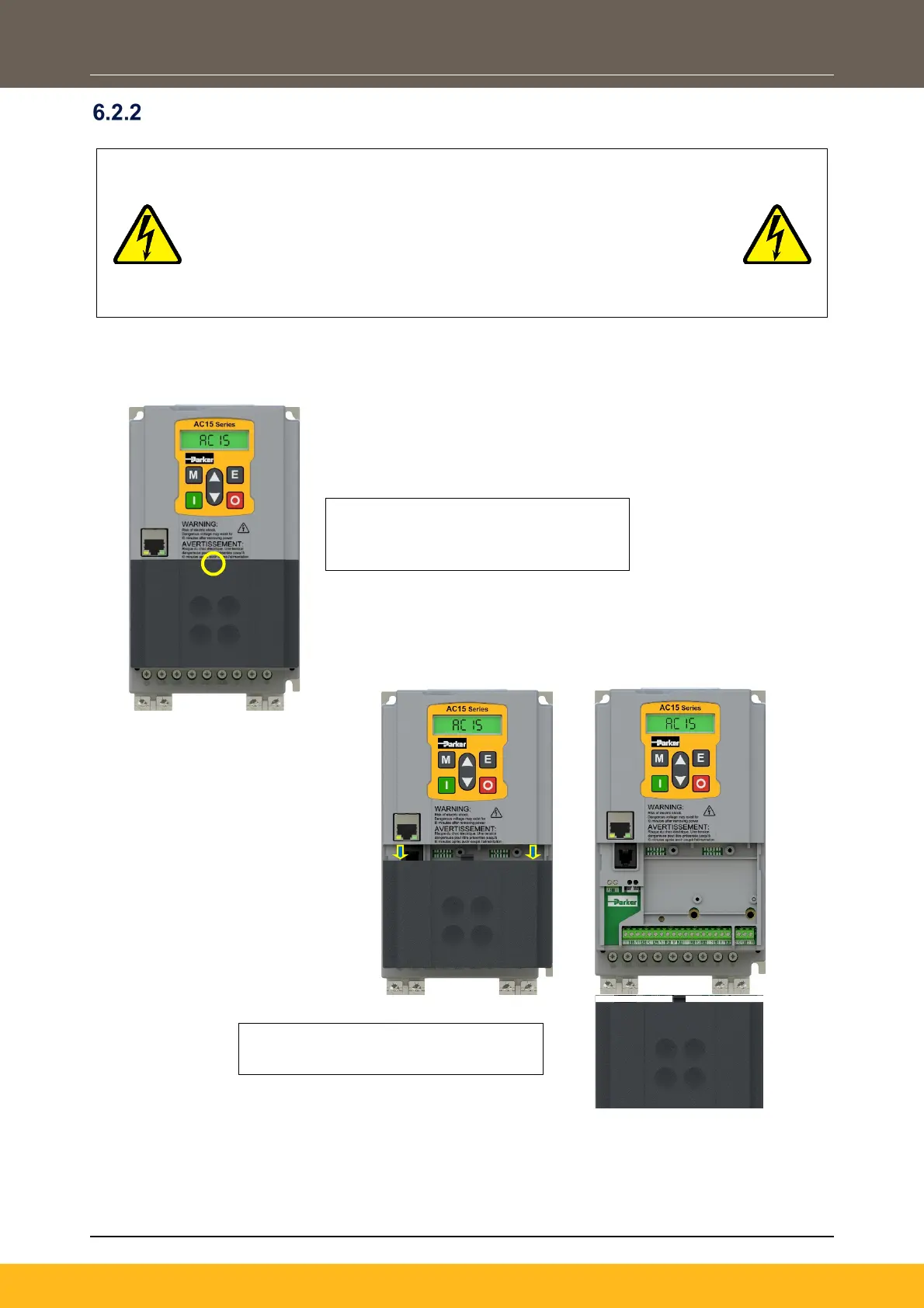
Terminal Cover Removal
The control module terminal cover must be removed to gain access to the control terminals for wiring.
To refit the terminal cover, perform the steps in reverse.
1. Apply pressure to the center of the
top edge of the terminal cover to
disengage the retention clip.
2. Now slide the cover down and pull
away from the control module.
 Loading...


