DOC-0017-03-EN: AC15 Series - Hardware Installation Manual
80 (125) DOC-0017-03-EN-B 04.04.2023
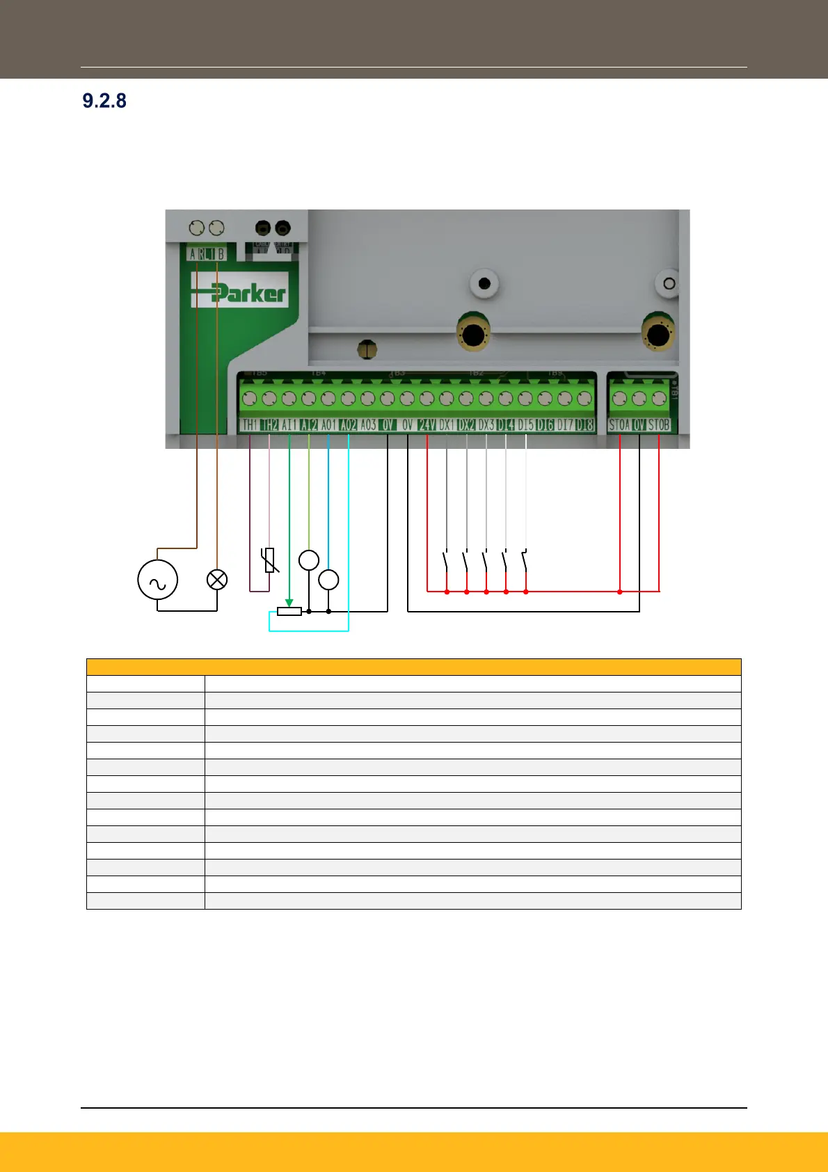
Application ‘5’: PID
A simple application using a Proportional-Integral-Derivative 3-term controller. The setpoint is taken from
AIN1, with feedback signal from the process on AIN2. The scale and offset features of the analogue input
blocks may be used to correctly scale these signals. The difference between these two signals is taken as
the PID error. The output of the PID block is then used as the drive setpoint.
110-230Vac (or 24Vdc) voltage supply
Healthy: Relay output (to lamp)
Motor Thermistor ‘+’ connection
Motor Thermistor ‘-’ connection
Process Setpoint (%) – input 1: 0-10V variable input (from potentiometer)
Process Feedback (%) – input 2: 4-20mA variable input (from current source)
Speed Demand (%): 0-10V variable output (to voltmeter)
Value = 100%: 0-10V variable output (+10V fixed reference voltage)
Run Forward: 24V digital input
Remote Reverse: 24V digital input
Not Stop: 24V digital input
Not Coast Stop: 24V digital input
STO DISABLED (drive operational)
S

 Loading...


