DOC-0017-03-EN: AC15 Series - Hardware Installation Manual
DOC-0017-03-EN-B 04.04.2023 81 (125)
Application ‘6’: Aux Comms
Aux Comms is designed to reproduce the Aux Comms macro/template from the legacy 650 range of drives.
The default method of communications for this macro is Modbus TCPIP, and the master controller must be
configured with a mapping that connects to the points shown in red text within the DSELite template.
Refer to the ‘AC15 Series – Software Reference’ Manual (DOC-0017-05) for instructions on configuring
base Modbus TCPIP communications.
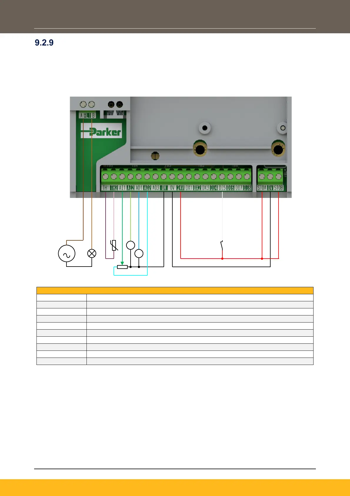
110-230Vac (or 24Vdc) voltage supply
Healthy: Relay output (to lamp)
Motor Thermistor ‘+’ connection
Motor Thermistor ‘-’ connection
Remote Setpoint (%) – input 1: 0-10V variable input (from potentiometer)
Remote Setpoint ‘Trim’ (%) – input 2: 4-20mA variable input (from current source)
Speed Demand (%): 0-10V variable output (to voltmeter)
Value = 100%: 0-10V variable output (+10V fixed reference voltage)
Not Coast Stop: 24V digital input
STO DISABLED (drive operational)
S

 Loading...


