DOC-0017-03-EN: AC15 Series - Hardware Installation Manual
92 (125) DOC-0017-03-EN-B 04.04.2023
EMC Installation Guidance
Protective Earth (PE) Connections
Local wiring regulations take precedence and may require the protective
earth connection of the motor to be connected locally, i.e., not as specified
in these instructions. This will not cause shielding problems because of
the relatively high RF impedance of the local earth connection.
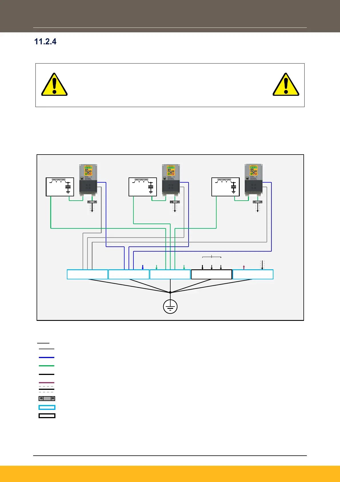
When installing an AC15 in a control cubicle, Parker recommends using a star-point earthing method where
‘noisy’ and ‘clean’ earths are separated out. Four separate earth bus bars, three of which are insulated from
the mounting panel, connect to a single earth point (star point) near the incoming safety earth from the main
supply:
CUBICLE BACK PANEL
Incoming Safety Earth (PE)
1. ‘Clea n’ Earth: Digital 3. Metal Wo rk Earth 1. ‘Clea n’ Earth: Analogue 2. ‘Dirty’ Earth 4. Signal / Control Screen
Doors
Frame
Back
Pan el
Cubicle
PE PE PE
Screen ed Cable
(To Motor)
Screen ed Cable
(To Motor)
Screen ed Cable
(To Motor)
STAR POINT EART H
Screened Signal / Control
Cable
Unsc r een ed C abl e
24Vdc
Control
230Vac
Control
110Vac
Control
‘CLEAN’ Analogue Earth Cables
‘CLEAN’ Digital Earth Cables
Screened Multi-Core Cables
U-Clip Connected to Back Panel
Busbar Insulated from Back Panel
Busbar Connected to Back Panel
 Loading...


