DOC-0017-03-EN: AC15 Series - Hardware Installation Manual
DOC-0017-03-EN-B 04.04.2023 47 (125)
STO Functional Description
STO is a means of preventing an inverter from delivering rotational force to its connected electric motor.
Please refer to EN61800-5-2:2017 para 4.2.3.2 for the formal definition.
To ensure a high degree of safety, two independent STO control channels are implemented in hardware,
providing the safety sub function STO. The STO circuits in the inverter are designed such that a fault in one
control channel will not affect the other channel’s ability to prevent the drive from starting, i.e., the STO
function of the inverter is tolerant to any single fault. It may not be tolerant to an accumulation of faults. This
is in keeping with its declared safety ratings. For complete STO functionality, it is necessary to use the
motor with the correct motor cable and correct STO input wiring.
STO always overrides any attempt to start the drive. If one or both STO control inputs is requesting the
STO function, the drive will not start, even if for example, the drive’s software malfunctions and tries to
cause the motor to turn.
The STO function is implemented in hardware; it overrides all software activities. The only software
involvement is to report the STO status to the user via the onboard inverter display or remote keypad
(MMI), serial communications link, or user terminal as defined by the drive configuration.
8.2 Alignment to European Standards
EN ISO13849-1:2015 (Safety of machinery – Safety-related parts of
control systems)
STO aligns internally to the following aspects of this standard:
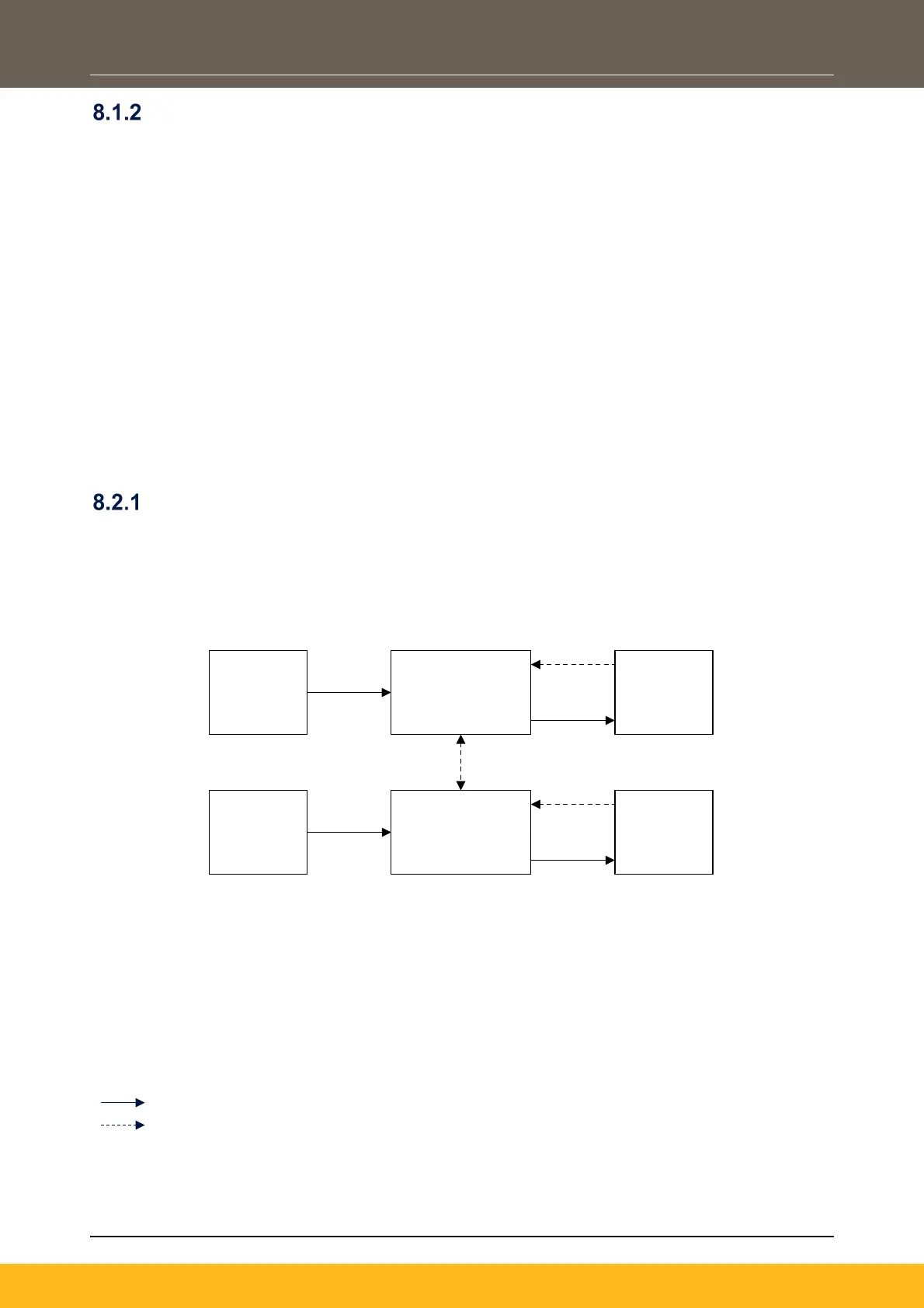
1. Architecture According to Category 3:
Where:
L2
O2
= Methods of Enabling/Disabling Output Power
Devices
mxy
X
= Reasonably Practicable Fault Detection
I1
L1
O1
I2
L2
O2
m1a
m2a
m1b
m2b
1
2
 Loading...


