DOC-0017-03-EN: AC15 Series - Hardware Installation Manual
DOC-0017-03-EN-B 04.04.2023 77 (125)
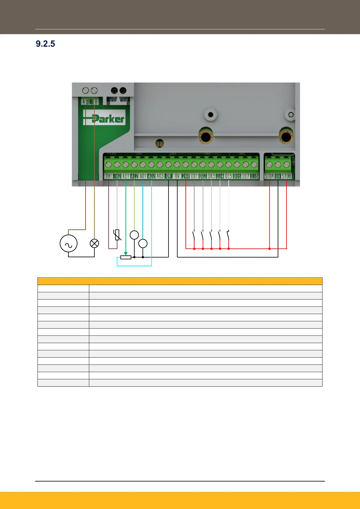
Application ‘2’: Auto / Manual
Two Run inputs and two Setpoint inputs are provided. The Auto/Manual switch selects which pair of inputs
is active.
The Application is sometimes referred to as Local/Remote.
110-230Vac (or 24Vdc) voltage supply
Healthy: Relay output (to lamp)
Motor Thermistor ‘+’ connection
Motor Thermistor ‘-’ connection
‘Manual’ Remote Setpoint (%): 0-10V variable input (from potentiometer)
‘Auto’ Remote Setpoint (%): 4-20mA variable input (from current source)
Speed Demand (%): 0-10V variable output (to voltmeter)
Value = 100%: 0-10V variable output (+10V fixed reference voltage)
‘Manual’ Run: 24V digital input
‘Auto’ Run: 24V digital input
Auto / Manual Select: 24V digital input
Remote Reverse: 24V digital input
Not Coast Stop: 24V digital input
STO DISABLED (drive operational)
S
 Loading...


