DOC-0017-03-EN: AC15 Series - Hardware Installation Manual
DOC-0017-03-EN-B 04.04.2023 79 (125)
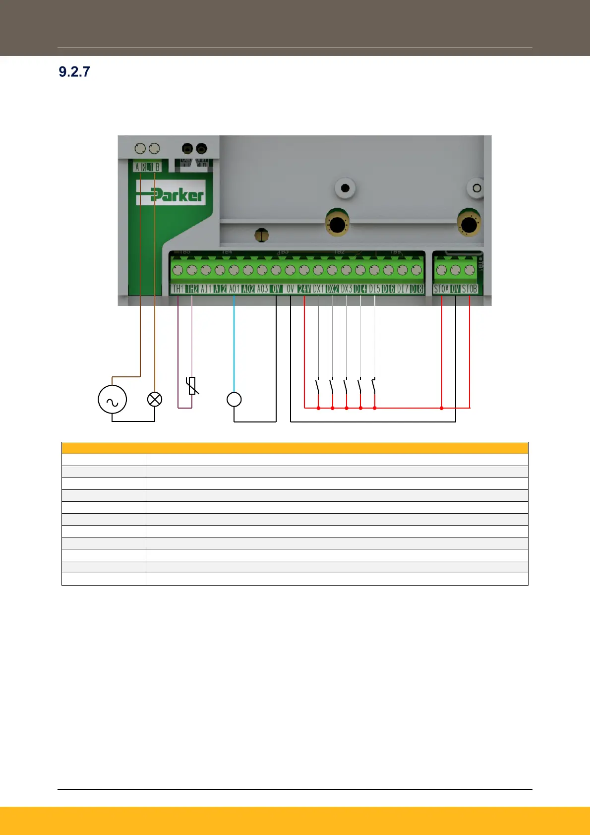
Application ‘4’: Raise / Lower
This Application mimics the operation of a motorised potentiometer. Digital inputs allow the setpoint to be
increased and decreased between limits. The limits and ramp rate can be set using the keypad.
The Application is sometimes referred to as Motorised Potentiometer.
110-230Vac (or 24Vdc) voltage supply
Healthy: Relay output (to lamp)
Motor Thermistor ‘+’ connection
Motor Thermistor ‘-’ connection
Speed Demand (%): 0-10V variable output (to voltmeter)
Run Forward: 24V digital input
Raise / Lower Reset: 24V digital input
Not Coast Stop: 24V digital input
STO DISABLED (drive operational)
S

 Loading...


