DOC-0017-03-EN: AC15 Series - Hardware Installation Manual
DOC-0017-03-EN-B 04.04.2023 27 (125)
3ø, 230V Products:
Frame
Power
Line Y-Cap)
Y1 ‘VAR’ (VDR)
Link Y-Cap)
1
5
3ø, 400V Products:
Frame
Motor
Power
J1 ‘EMC’ (AC
Line Y-Cap)
Y1 ‘VAR’ (VDR)
J2 ‘P -> PE’ (DC
Link Y-Cap)
1
2
3
4
5
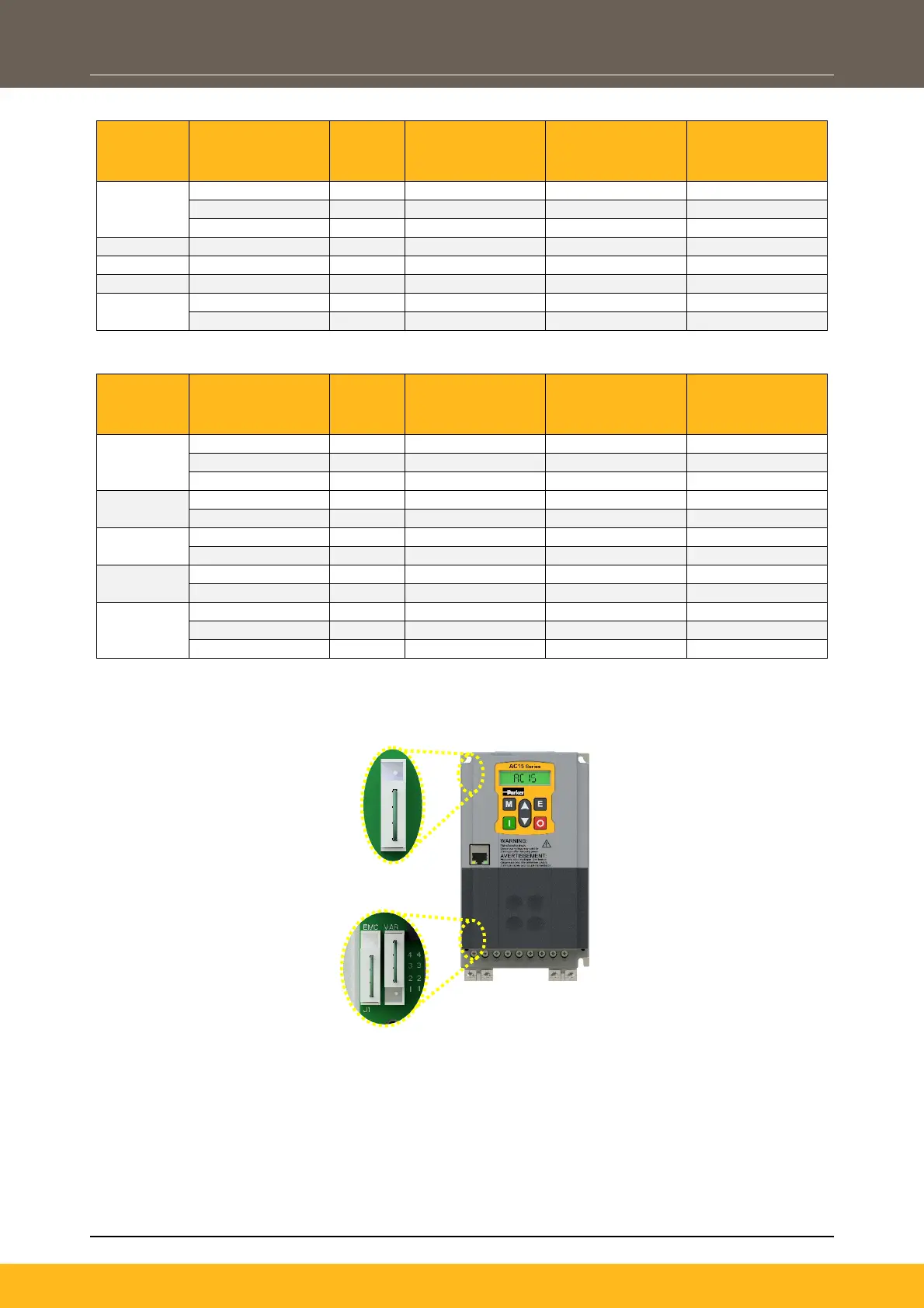
Approximate Link Locations:
Note: Link positions vary slightly between products. Image shows approximate link locations:
To access the links, it is necessary to open the product:
1. Remove:
- Frame 1: 3x Power Stack cover fixings (1x top, 2x bottom) from the product
- Frames 2 – 5: 4x Power Stack cover fixings (2x top, 2x bottom) from the product.
2. Carefully lift the power stack cover with the control module attached - just enough to adjust the link
positions. Removing the link completely is the same as placing the links in the ‘disconnected’ (pin 2
– 4) position.
Note: All power cables must be removed from the product to access the links.
J2 DC Link
Y-Cap Link
J1 ‘EMC’ AC
Line
Y-Cap &
Y1 ’VAR’
VDR Links

 Loading...


