DOC-0017-03-EN: AC15 Series - Hardware Installation Manual
26 (125) DOC-0017-03-EN-B 04.04.2023
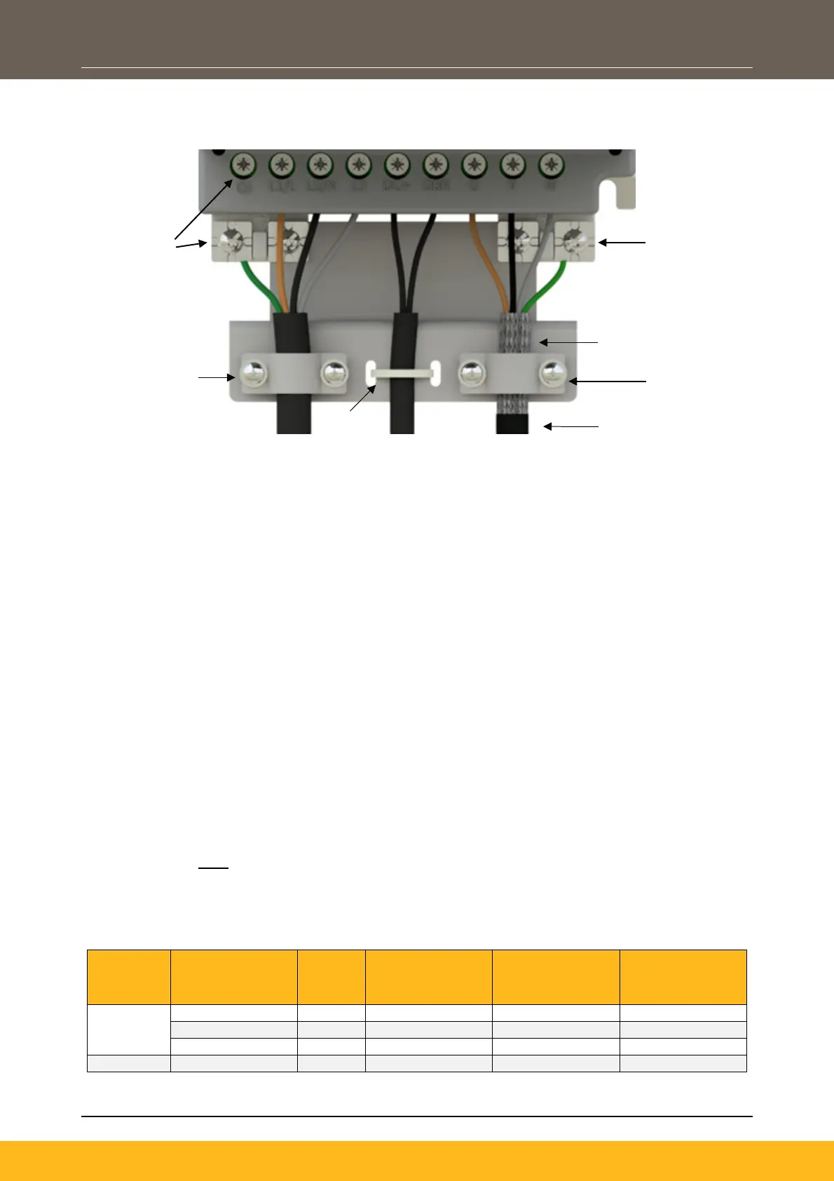
Cable Connections With Wiring Bracket Fitted
Below is an example of how to correctly terminate the motor screen onto the wiring bracket:
Y-Capacitors & VDR Earth Disconnects
The AC15 products are fitted with EMC filter capacitors connected between ‘live’ AC Line (and in some
instances DC Link) circuits to earth. These capacitors are referred to as Y-Capacitors.
In some system applications where RCD’s are in circuit, or where the drive is connected on an IT or open
delta supply, these Y-Capacitors may need to be disconnected from earth. Removable links are provided to
enable users to perform this task.
By default:
- AC Line Y-Caps are connected to earth (‘EMC’ connector ‘J1’, is fitted in position 1 – 3).
- DC Link Y-Caps are connected to earth (‘P -> PE’ connector ‘J2’ is fitted in position 1 – 3).
Most products are also fitted with input line voltage suppression devices connected between ‘live’ AC Line
circuits to earth. These suppression devices are referred to as VDRs.
In some system applications where the product is exposed to large, transient voltage events on the power
supply that it is connected to, it is recommended that the VDRs are connected to earth as a means of
protecting the drives input rectification stage. Removable links are provided to enable users to perform this
task.
By default:
- VDRs are NOT connected to earth (‘VAR’ connector ‘Y1’, is fitted in position 2 – 4).
A summary of links fitted to each product is shown below:
1ø, 230V Products:
Frame
Size
Product Code
Motor
Power
(kW)
J1 ‘EMC’ (AC
Line Y-Cap)
Link:
Y1 ‘VAR’ (VDR)
Link:
J2 ‘P -> PE’ (DC
Link Y-Cap)
Link:
1
Motor cable screen
exposed and clamped
underneath saddle.
Motor earth
connected to
chassis
earth
Supply earth
connected to
either the PE
terminal, or
chassis
earth
Resistor Cable
(2 Core)
Clamp
(3 Core + E
Screened)
Supply Cable
(2/3 Core + E)
Ty-Wrap

 Loading...


