DOC-0017-03-EN: AC15 Series - Hardware Installation Manual
DOC-0017-03-EN-B 04.04.2023 29 (125)
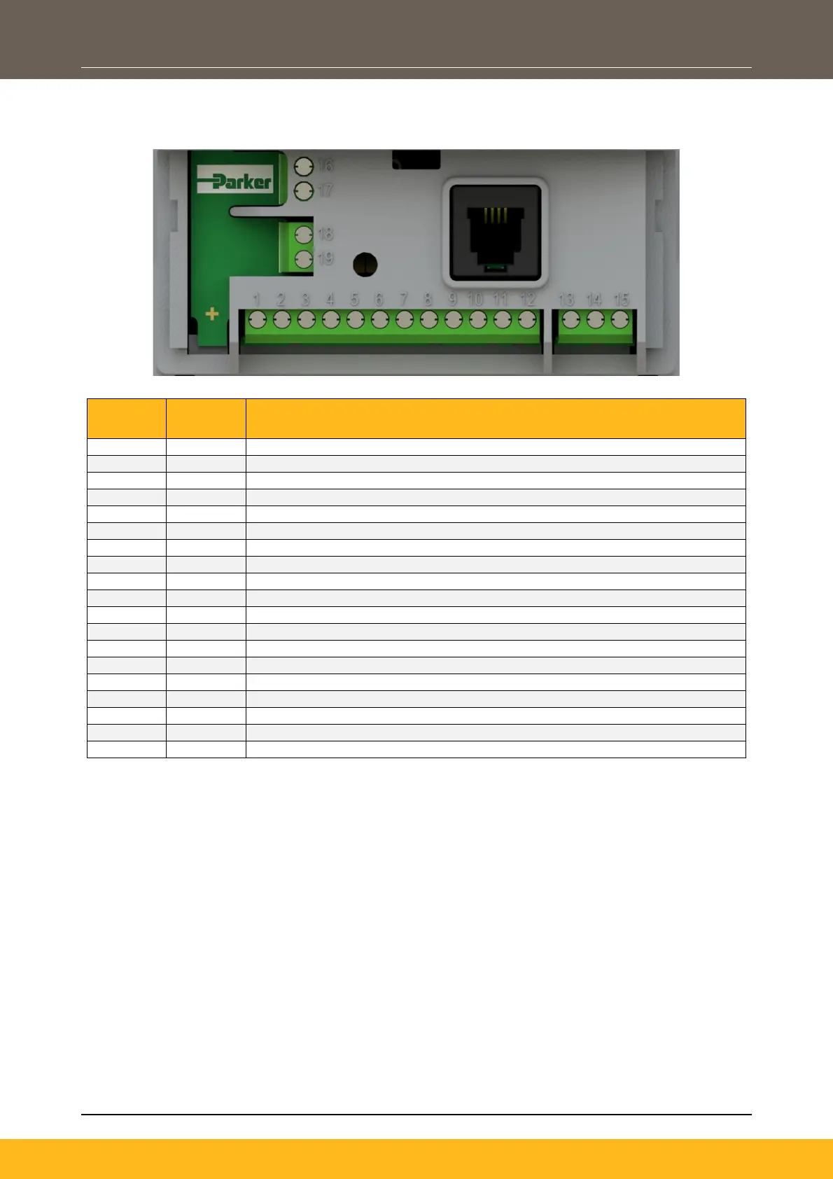
Terminal Identifications
Frame 1:
Description
Relay Output 1 (Contact A)
Relay Output 1 (Contact B)
Analogue Input 1 (±10V, 0-10V, 0-20mA, 4-20mA)
Analogue Input 2 (±10V, 0-10V, 0-20mA, 4-20mA)
Analogue Output 1 (0-10V, 0-20mA, 4-20mA)
Analogue Output 2 (0-10V, 0-20mA, 4-20mA)
0V Reference For Analogue & Digital I/O / External 0V Auxiliary Input
User +24V Output / External +24V Auxiliary Input
Digital Input / Output 1 (24V Configurable)
Digital Input / Output 2 (24V Configurable)
Digital Input 4 / Encoder Channel A Input (High Speed)
Digital Input 5 / Encoder Channel B Input (High Speed)

 Loading...


