DOC-0017-03-EN: AC15 Series - Hardware Installation Manual
14 (125) DOC-0017-03-EN-B 04.04.2023
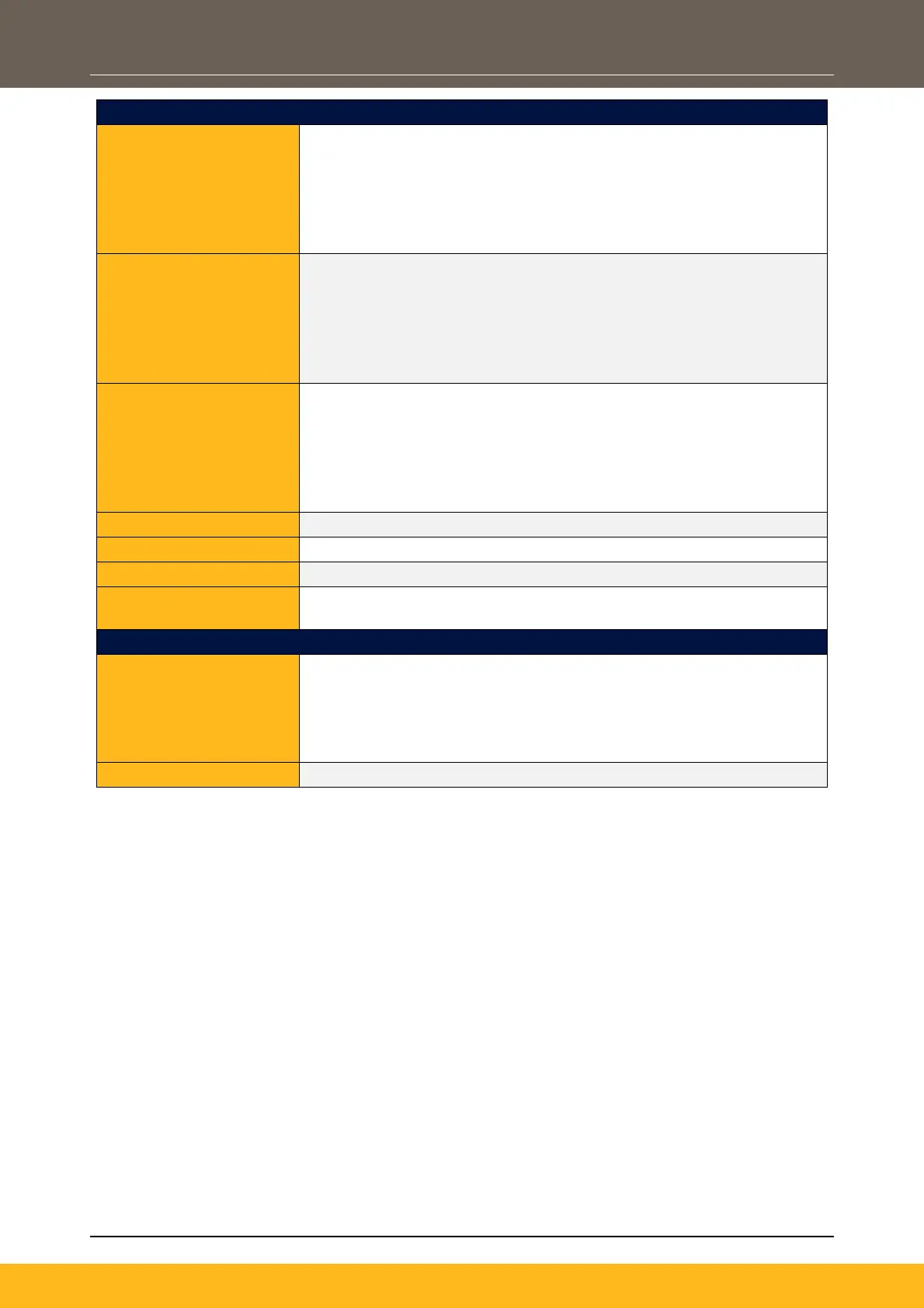
Analogue Inputs:
- 2x Configurable Inputs: Voltage Mode (0-10V) / Current Mode (0-
20mA, 4-20mA)
Frames 2 – 5:
- 2x Configurable Inputs: Voltage Mode (± 10V, 0-10V) / Current
Mode (0-20mA, 4-20mA)
Analogue Outputs:
- 2x Configurable Outputs: 2x Voltage Mode (0-10V) / Current
Mode (0-20mA)
Frames 2 – 5:
- 3x Configurable Outputs: 2x Voltage Mode (0-10V) / Current
Mode (0-20mA), 1x Voltage Mode (± 10V, 0-10V)
Digital Inputs:
- Up to 6x Configurable 24Vdc Inputs (4x Dedicated Inputs with
common selectable pull-ups for active low operation)
Frames 2 – 5:
- Up to 8x Configurable 24Vdc Inputs (6x Dedicated Inputs with
common selectable pull-ups for active low operation)
Up to 2x Configurable 24Vdc Outputs
1x Configurable Relay Outputs
1x User +24V Reference Voltage Output
External +24V Auxiliary
Input:
1x +24Vdc Input (PELV)
Base Communication Ports:
Ethernet:
Frame 1:
- DSELite / Web HTTP Server / Modbus TCP
Frames 2 – 5:
- DSELite / Web HTTP Server / Modbus TCP / EtherNet/IP
1x RJ11 Port for remote 6901 MMI

 Loading...


