EasyManuals Logo

Parker AC15 Series User Manual

Parker AC15 Series
125 pages
To Next Page IconTo Next Page
To Previous Page IconTo Previous Page
Page #31 background imageLoading...
Page #31 background image
DOC-0017-03-EN: AC15 Series - Hardware Installation Manual
DOC-0017-03-EN-B 04.04.2023 31 (125)
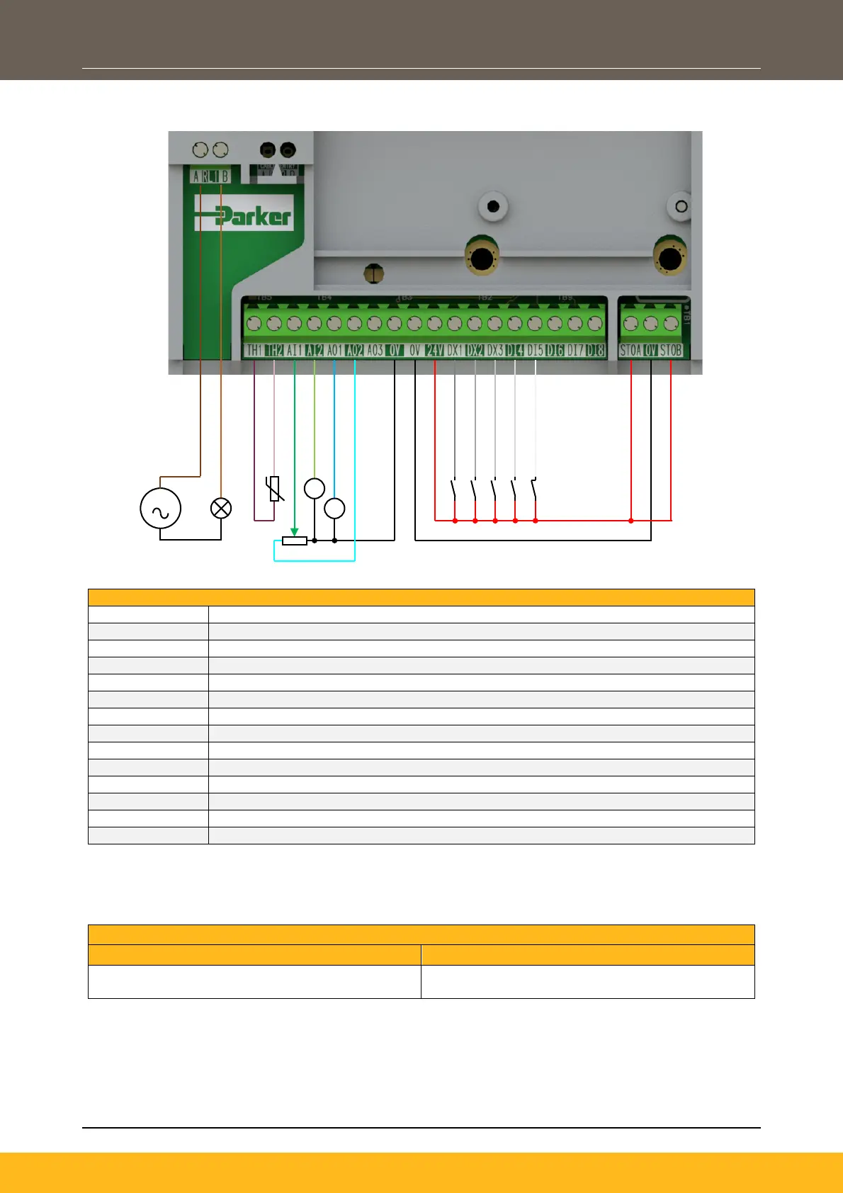
Wiring Example
RL1A
110-230Vac (or 24Vdc) voltage supply.
RL1B
Relay output (to lamp).
TH1
Motor Thermistor ‘+’ connection.
TH2
Motor Thermistor ‘-’ connection.
AI1
0-10V variable input (from potentiometer)
AI2
4-20mA variable input (from current source)
AO1
0-10V variable output (to voltmeter)
AO2
0-10V variable output (+10V fixed reference voltage)
DX1
24V digital input
DX2
24V digital input
DX3
24V digital input
DI4
24V digital input
DI5
24V digital input
STO
STO DISABLED (drive operational)
Terminal Block Wire Range
The control board terminal wire range is as follows:
Terminal Wire Range
Min
Max
0.2mm
2
(24 AWG)
1.0mm
2
(18 AWG)
Wire sizes for Europe should be chosen with respect to the operating conditions and your local National
Electrical Safety Installation Requirements. Local wiring regulations always take precedence.
V
V
S

Table of Contents

Questions and Answers:

Question and Answer IconNeed help?

Do you have a question about the Parker AC15 Series and is the answer not in the manual?

Parker AC15 Series Specifications

General IconGeneral
BrandParker
ModelAC15 Series
CategoryDC Drives
LanguageEnglish

Related product manuals