DOC-0017-03-EN: AC15 Series - Hardware Installation Manual
DOC-0017-03-EN-B 04.04.2023 95 (125)
Cable routing should be planned in a way that segregates certain cable types to meet EMC compliance:
- Use the shortest possible motor cable lengths.
- When connecting multiple motors to a single inverter, use a star junction point for motor cable
connections. Use a metal box with entry and exit cable glands to maintain shield integrity.
- Keep electrically ‘noisy’ and ‘sensitive’ cables apart.
- Keep electrically ‘noisy’ and ‘sensitive’ parallel cable runs to a minimum. Separate parallel cable
runs by at least 0.25 meters. For runs longer than 10 meters, separation should be increased
proportionally. For example, if the parallel runs were 50m, then the separation would be (50/10) x
0.25m = 1.25m.
- ‘Sensitive’ cables should cross ‘noisy’ cables at 90°.
- Never run ‘sensitive’ cables close or parallel to either the Motor, DC Link or Dynamic Brake circuits
for any distance.
- Never run AC Line Supply, DC Link or Motor cables in the same bundle as either the Signal /
Control or Feedback cables, even if they are screened.
- Ensure the optional External EMC Filter input and output cables are separately routed and do not
couple across the filter.
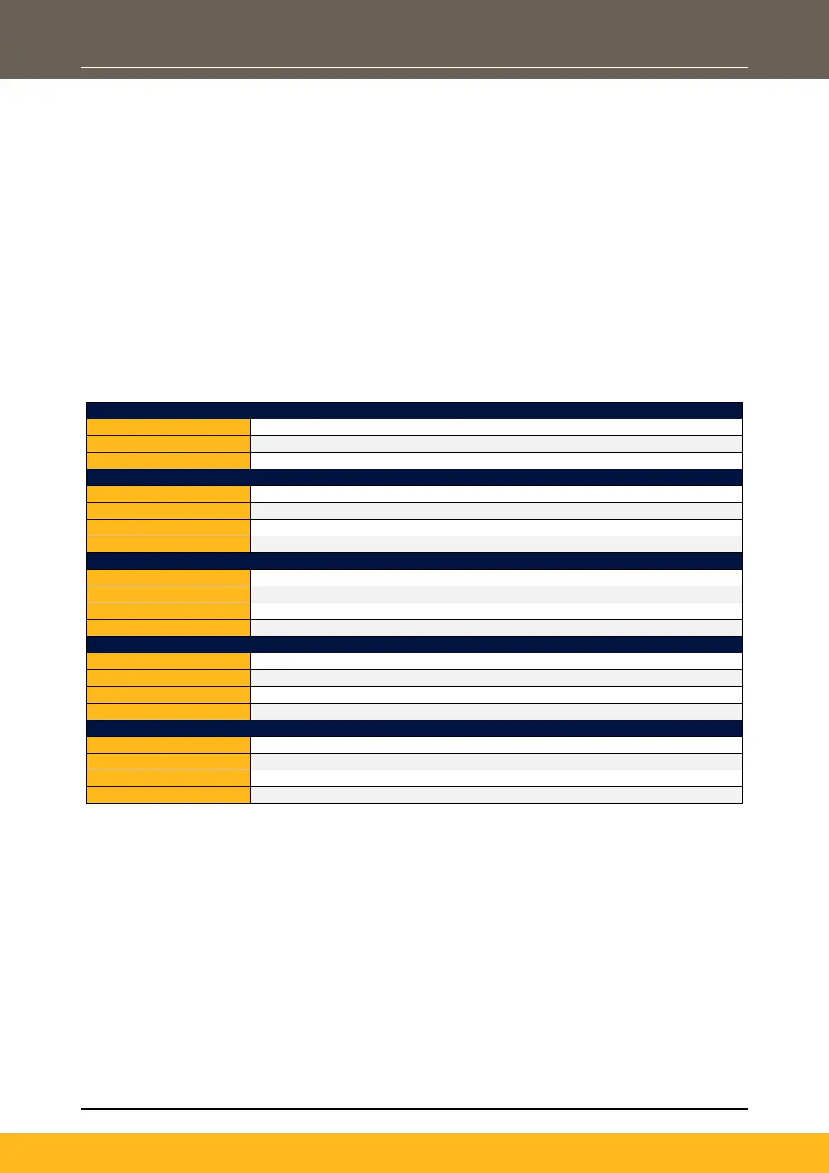
From all other wiring (clean)
External EMC Filter to Inverter Input Cable
From all other wiring (noisy)
From all other wiring (noisy)
50m (up to 300m with an output choke)
From all other wiring (noisy)
From all other wiring (sensitive)
Mitigating Radiated Emissions
To mitigate against the effects of radiated emissions, the following considerations should be made when
installing the Inverter witihin a Variable Speed Drive (VSD) system:
1. Equipment Placement
Magnetic / Electric Field sensitive equipment should not be placed within 0.25 meters of the
following components in the VSD system:
- Variable Speed Drive (VSD)
- EMC Output Filters
- Input or Output Chokes / Transformers
- The cable between VSD and motor (even when screened/armoured)
- Connections to external braking chopper and resistor (even when screened/armored)
- AC/DC brushed motors (due to commutation)
- DC link connections (even when screened/armoured)
- Relays and contactors (even when suppressed)

 Loading...


