76180 EM -29/73-
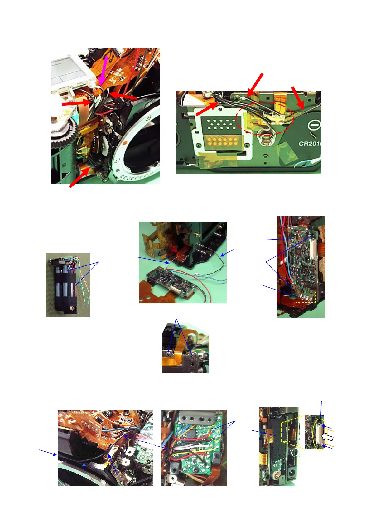
⑫ Arrange the lead wires for CE marking as shown in the figure below.
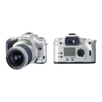
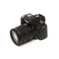
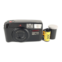
7. 0-Q200・0-T800 (Flash P.C. Board assy.・Power P.C. Board assy.)
① Pass T905 (Power supply cable) through between the main plate and bottom plate.
② 0-T800
③ CNL-D1.7x2.5 (2pcs.)
④ Solder 4 lands.
⑤ A4, 0-Q200
⑥ CNL-D1.7x2.5 (2pcs.)
⑦ Connect the flexible board of T100 to the connector terminal of 0-T800.
⑧ Stick BT (25x10) on the flexible board and main capacitor.
⑨ Solder 2 lead wires. (Red: T800, Black: T900)
①
T905
③
④
②
⑤
⑧
⑦
⑨
⑥