76180 EM -36/73-
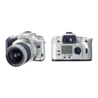
④ Connect the flexible board of T100 to the connector terminal of T700.
⑤ Connect the flexible board of T100 to the connector terminal of T600.
16. [CONF] Function Check II
[Required equipment] CF card for the firmware (FW), Color video monitor, Video cable (I-VC2),
Battery adaptor (Jig: Battery grip D-BG1), Regulated DC power supply (8V・3A), DC cord (Jig),
AC Adapter (D-AC10)
[Preparation] Connect the video cable to the color video monitor.
16-1. Battery・DC Power Input, Connection between 0-T100 and 0-T600
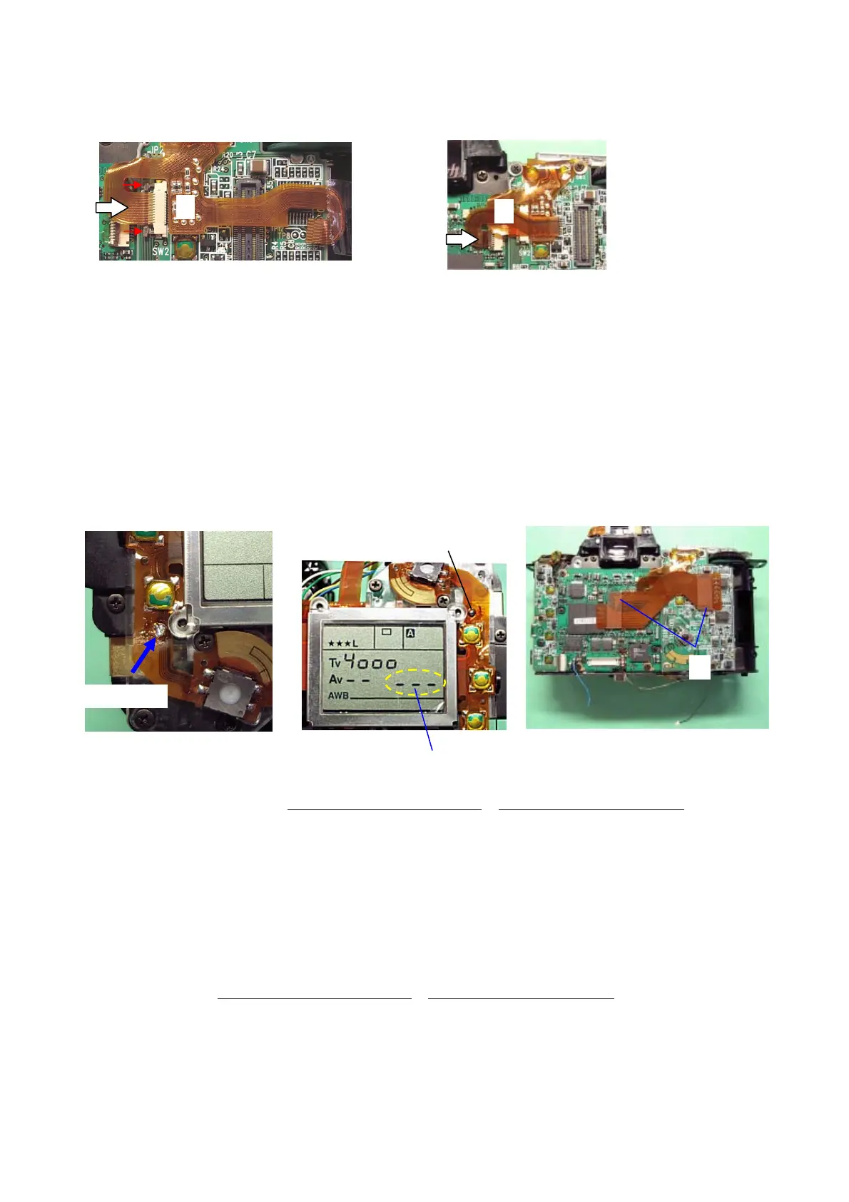
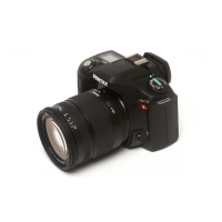
① Short the main switch land on T100 by soldering as shown in the figure below.
② Connect the battery adaptor to the DC power supply and set the voltage to DC5.6V (3A).
③ Temporarily install the bottom cover by A67x2 (5mm).
④ Attach the battery adaptor to the camera. At this time, there must be neither short nor
Leakage. (Main SW ON: Metering OFF: Ave.180mA
*, Metering ON: Ave.370mA*)
* When the power is supplied by the Battery grip connection terminal.
[CAUTION] When the over-current occurs, remove the camera from the power supply at once.
⑤ When 0-T600 is connected to 0-T100 successfully, [- - -] must be appeared on the LCD panel.
⑥ Remove the battery adaptor from the camera.
⑦ Connect the DC cord to the power supply and set the voltage to DC6.5V (3A).
⑧ Connect the DC cord to the camera and then the camera will be turned ON. At this time,
there must be neither short nor Leakage.
(Main SW ON: Metering OFF: Ave.240mA
*, Metering ON: Ave.420mA*)
* When the power is supplied by the DC input terminal.
⑨ Disconnect the DC cord, and the LCD display must be disappeared.
⑩ Connect both connector terminal of 0-T950 to 0-T600 and 0-T700.
SW Land
⑩
④
⑤
①
⑤