76180 EM -48/73-
④
⑧
⑨
⑩
⑤
⑥
⑦
⑤
⑭
⑫
⑪
⑪
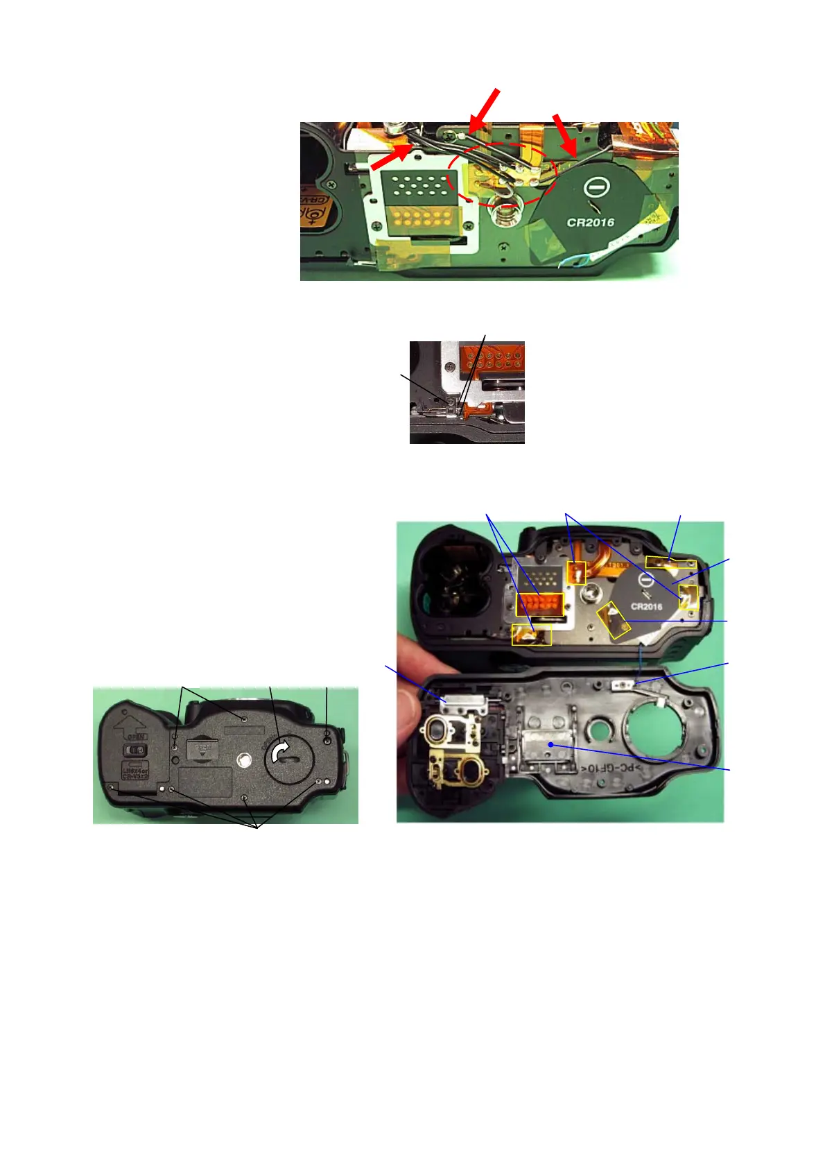
25. Arranging the lead wires for CE marking
26. A401 (Bottom Cover)
① A424
② CNL-B1.4x1.6
③ Solder two lands.
④ A434
⑤ Stick A425 x3 (10x20)
⑥ Stick A426 (8x14)
⑦ Stick A427 x2 (8x10)
⑧ Solder a blue lead wire to A432 (A401).
⑨ A421 (Connector cover)
⑩ 0-A412 (Battery cover), A419(Shaft)
⑪ A67x6 (Screw)
⑫ A61 (Screw, 2mm)
⑬ Close the battery cover.
⑭ A435, A431 (Backup battery, cover)
27. [CONF] Checking the back-up function
① Confirm that the screen for setting the [Date] is not displayed when the main switch is
turned ON once.
② Turn OFF the main switch.
③ Remove the battery from camera, and then turn ON the main switch.
④ Turn OFF the main SW, and then insert the battery to camera.
⑤ Confirm that the screen for setting the [Date] is not displayed when the main switch is
turned ON again.
Battery consumption at the terminal of back-up battery:
When the terminal voltage is 3.0V: 7.5μA average (There is a pulse wave as 10μA per second.)
③
①②