76180 EM -31/73-
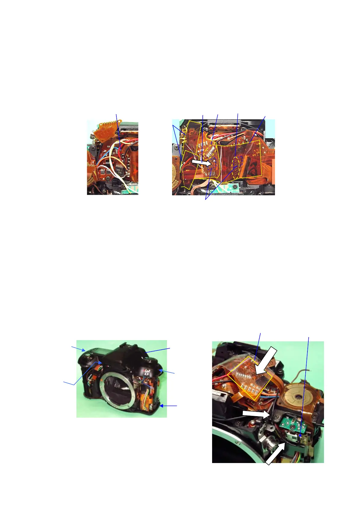
10. Around Pentaprism (1)
① Solder a blue lead wire. ・・・ 0-T800
② Solder 7 lands.・・・ 0-J100
③ Stick T64 (20x50) on 0-T100 as shown in the figure below.
④ Stick 0-T100 by DT (5x5) as shown in the figure below.
⑤ Solder 7 lands.・・・ 0-O170
⑥ Stick T74 x2 (20x10) on 0-T100 as shown in the figure below.
11. [CONF] Function Check Ⅰ
[Required equipment] Regulated DC power supply (8V・3A), DC cord (Jig), Lens for checking
(e.g. FA50mmF1.4), Cable switch CS-205, Remote control F, Top cover (0-A301)
11-1. Preparation (The following preparation is required checking the function.)
① Temporarily solder a black lead wire No.6 (T800) to the upper right terminal of remote
control receiver.
② Stick PT (20x20) on the Penta-prism as indicated by arrow in the figure to prevent short
circuit.
③ Temporarily install 0-A301 by A61 (2.5mm), A62 (3.5mm) and A63 (4.2mm).
[CAUTION] Arrange the flexible boards and lead wires to outer side to prevent damage.
④ Temporarily install the bottom cover by A67x2 (5mm).
④
⑤
⑥
③
②
DT(5x5)
①
②
①
A62
(3.5mm)
A63(4.2)
A61(2.5)
③
④