15
13.6
13.3
13.2
13.7
13.3
13.6
13.4
13.2
13.2
13.4
CB 240 Climbing Formwork
Instructions for Assembly and Use – Standard Configuration
A1 Assembly of the CB 240 Platform
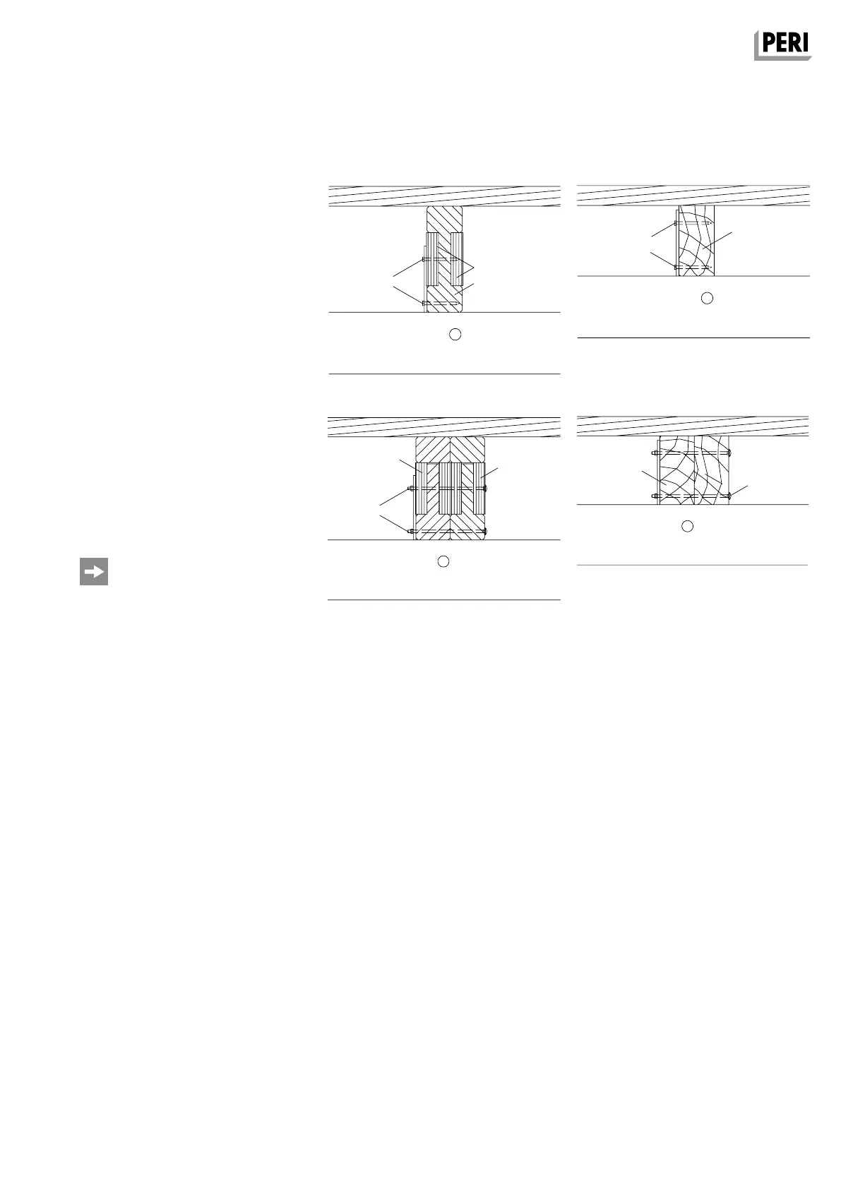
Fig. A1.12 Fig. A1.13
Fig. A1.14
Fig. A1.15
Double Girder Position
– plywood or 3-ply board (13.2)
– timber 8/16 (2x) or 16 x 16 (1x) (13.6)
– round head bolt M6 x 180 DIN 603
(13.4)
– GT 24 lattice girder (13.7)
(Fig. A1.14 + A1.15)
These drawings conform to Appendix
K15 of the type test issued by the State
Structural Inspectorate, Düsseldorf, test
certificate no. P31 – 95/91 and may only
be used in accordance with the afore-
mentioned type test.
Single Girder Position
– plywood or 3-ply board (13.2)
– hex. wood screw 6 x 80 DIN 571
(13.3)
– timber 8/16 (13.6)
– GT 24 lattice girder (13.7)
(Fig. A1.12 + A1.13)
GT 24 Girder Timber
AuV CB 240 EX.indb 15 29.06.16 09:44
 Loading...