12
CB 240 Climbing Formwork
Instructions for Assembly and Use – Standard Configuration
A1 Assembly of the CB 240 Platform
0.3
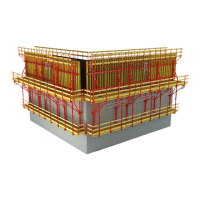
Fig. A1.03
83 mm 80 mm
240
2,398 m120 mm
82 mm 82 mm
C
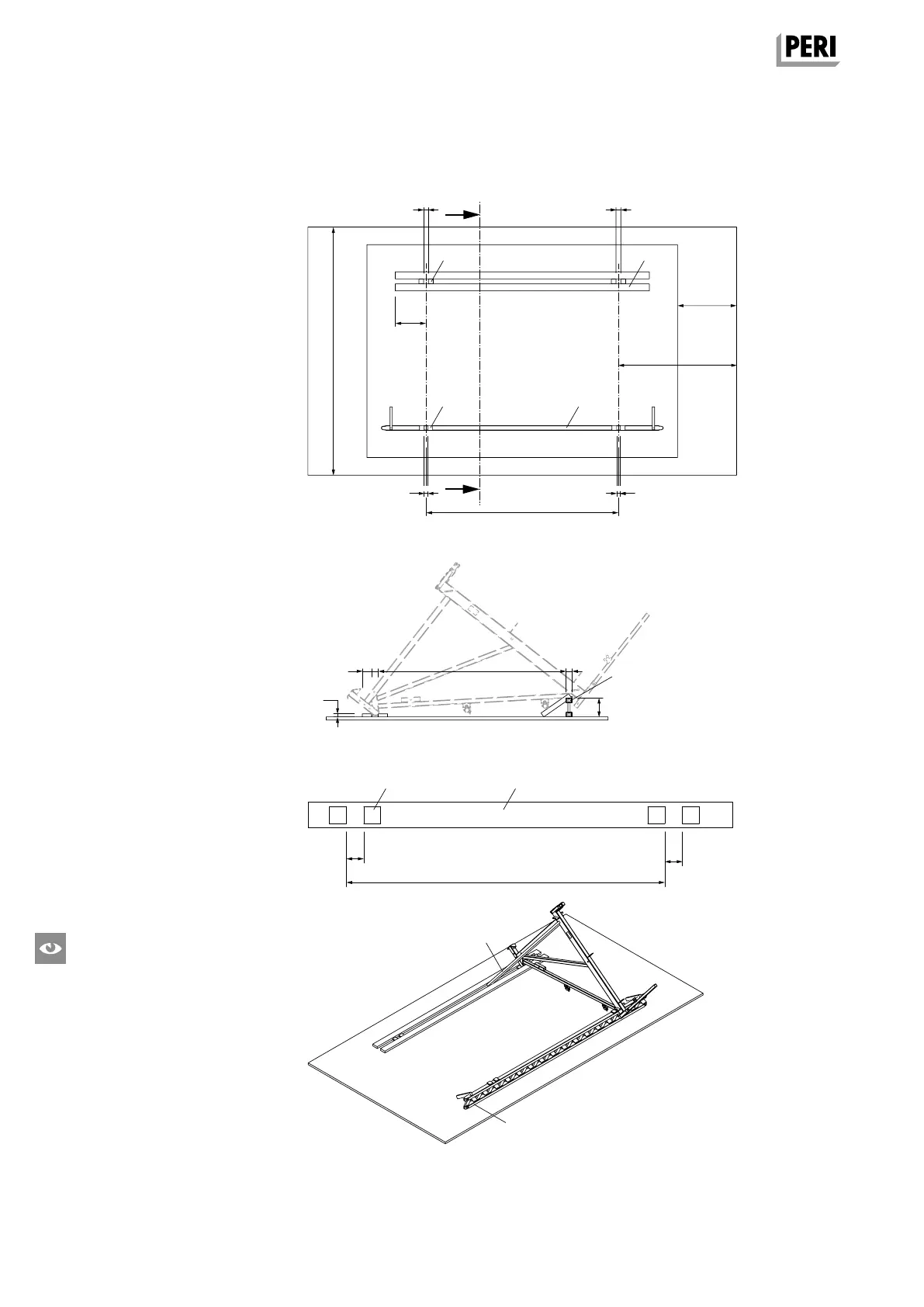
Fig. A1.02
Fig. A1.01
0.5
0.2
0.2
Required Resources
Equipment and Tools
Hammer, wire pins, plumb line, 4 screw
clamps with 300 mm clamping length,
circular saw, electric drill, HSS drill
Ø6mm, Ø 8 mm, min. L = 180 mm
072180 Ratchet Wrench 1/2”
102784 Socket SW 24 – 1/2”
029620 Socket SW 19 – 1/2”
072170 Socket SW 13 – 1/2”
072150 Power Wrench M14, ASB 636
072210 Power Screwdriver SCU 7 – 9
072220 Bit Holder
072230 Magnetic Holder
072140 Bit Points TX 30
031480 Socket Wrench SW 36
027212 Allen Key SW 14
031080 Drill Bit Ø 25 mm
Assembly Surface
Width: approx. 3.50 m.
Length: maximum platform width + min.
2.0 m.
Attach stop bars and support.
(Fig.A1.01)
Aids
– Locating Block (0.1) 12 plywood
blocks 21 x 80 x 80 mm.
– Support (0.2) h = approx. 24 cm, e.g.
GT 24 L = max. bracket spacing + 1.0 m.
– Stop Bars (0.3) 1 plank 40 x 120 mm
1plank 80 x 80 mm L = max. bracket
spacing + 1.0 m.
– Gauge for bracket spacing (0.4) 1
plank 40 x 120 mm L = bracket spacing
+ max. 1.0 m Formlining blocks (4).
(Fig. A1.02)
– Diagonal bracing for securing bracket
(0.5) 1 plank 40 x 120 mm, L = 2.0 m.
(Fig. A1.03)
Are the stop bars and support mounted
parallel to each other?
82 mm 82 mm
1,0 m
2,0 m
3,5 m
62 mm 62 mm
C
ca. 50 cm
2 stop bars
Support
Centre line of bra-
cket
Centre line of bra-
cket
Wall side
Section A-A
Guardrail side
A
A
Fig. A1.01a
0.2
0.1
0.1
0.1 0.4
AuV CB 240 EX.indb 12 29.06.16 09:44