23
CB 240 Climbing Formwork
Instructions for Assembly and Use – Standard Configuration
A2 Other Assembly Work
14.9
14.9
14.8
13B
14.1
14.2
Assembly of Foldable Hatch
The hatch is positioned in the moving
area of the formwork. If the access
ladder is to be used even if the form-
work is completely retracted, the
hatch is to be positioned in the can-
tilevered area of a corner platform.
– We recommend the hatch, as fea-
tured, to be installed close to the
bracket in order that personnel can
hold the spindle when climbing.
– Alternatively, the Sliding Hatch Cover
Item no. 051430 can be used. The
cut-out in the planking must be adap-
ted accordingly. Details are available
on request.
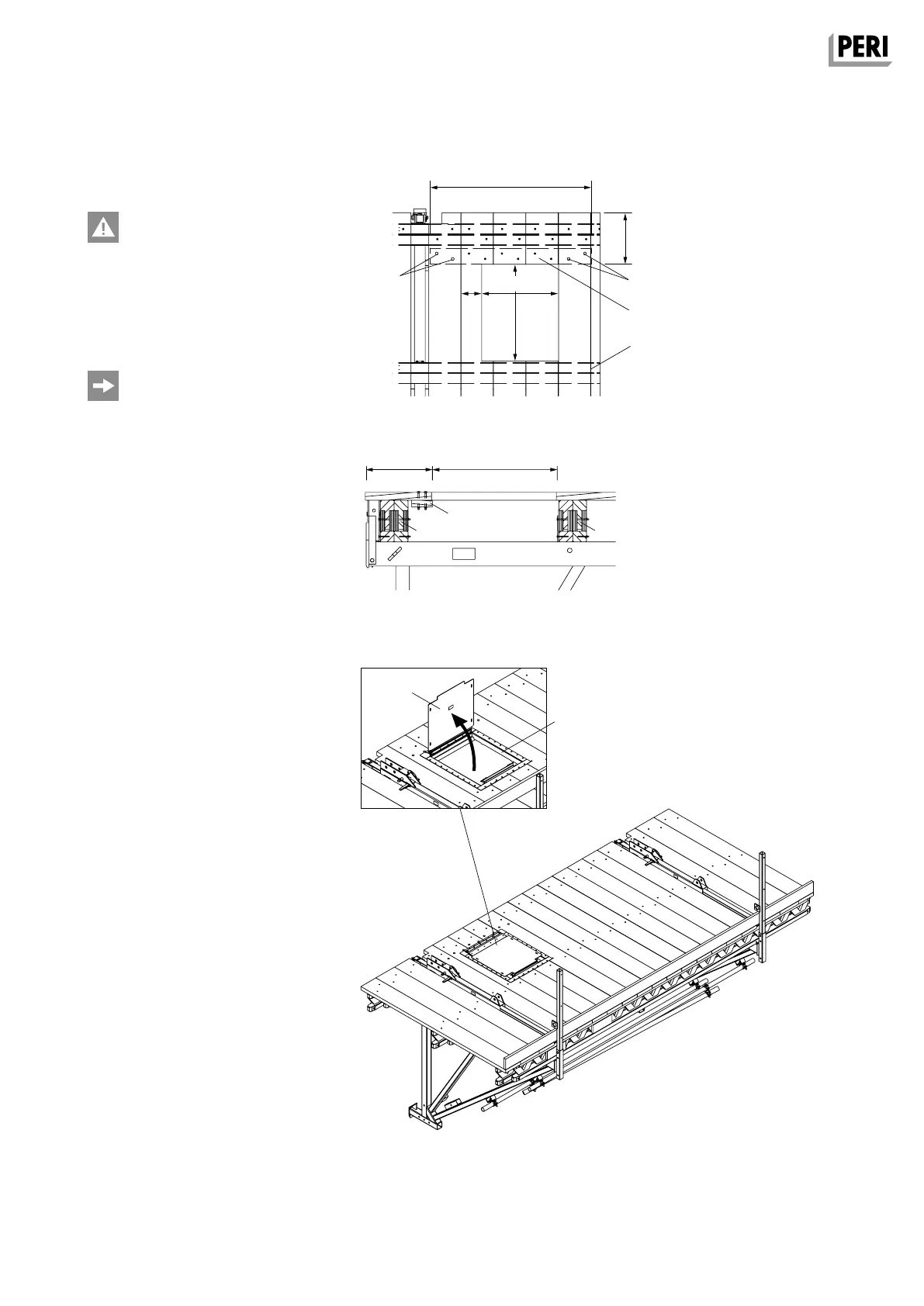
Pre-assembly
– For installation, a 72 x 57 cm cut-out
must be made in the planking bet-
ween the brackets.
– Ensure the remaining plank width is
> 10 cm.
– The cut-out is arranged flush against
the middle girder (13B).
– The truncated decking pieces are to
be supported on the wall-side girder
(13A) using timber (14.8), L = 120 cm,
min. 120 x 40 mm and bolted using
TORX 6 x 80.
– The timber (14.8) is bolted 2x in each
case to the lateral continuous plan-
king. F.H. Round head bolts DIN 603
M8 x 100 (14.9) with washer
ISO 7094 100 HV A8.
(Fig. A2.03 and Fig. A2.04)
Assembly
– Place hinged hatch 55 x 60-2 (14.1)
in the cut-out. The cover (14.2) opens
towards the wall side. (Fig. A2.05)
– Attach hatch frame to the planking
(approx. 20 x TORX 6 x 40).
(Fig. A2.06)
Fig. A2.03
1200
Fig. A2.06
Fig. A2.05
Section
Fig. A2.04
570
382 720
720
382
min
100
14.8
13A 13B
AuV CB 240 EX.indb 23 29.06.16 09:44