26
CB 240 Climbing Formwork
Instructions for Assembly and Use – Standard Configuration
B1 Work on the Construction Site
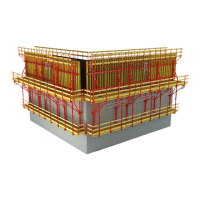
Fig. B1.01
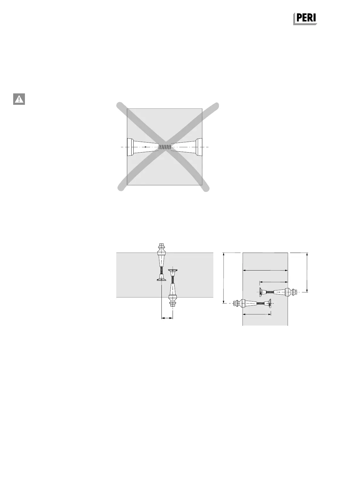
Fig. B1.03
Top view
horizontal offset
Anchoring
Safety Instructions
– Each CB Bracket must be individu-
ally anchored, and the loosening or
dismantling of the anchoring may
only take place on the side of the
load transfer. The positioning of
two cones against each other is not
allowed. (Fig. B1.01)
– If h
1
+ h
2
< d, the anchor positions
must be horizontally or vertically
offset. (Fig. B1.02 + B1.03)
– The correct installation of the clim-
bing anchor is to be checked before
being concreted in position. We re-
commend the compiling of an ac-
ceptance report.
– The climbing anchors must not be
used until the load-bearing capaci-
ty of the anchorage is sufficient.
– The threaded areas on the Screw-
On Cone-2 and Climbing Cone-2 as
well as the Threaded Plates DW 15
and DW 20 must always be com-
pletely screwed in.
– The required anchoring depth h
must not be achieved through a
r eduction of the screw-in depth.
– The tie rods must be chamfered at
both ends.
– Damaged anchoring components
must not be used.
Examples of damage:
– welding splashes on the tie rods,
– twisted tie rods,
– blocked threads,
– deformed cone cups,
– rough or scratched cone surfaces,
– missing dowel pin in the climbing
cone.
Section
vertical offset
CB 240 CB 160
min. 45 cm
≥ 10 cm
min. 35 cm
Fig. B1.02
h
2
d
h
1
AuV CB 240 EX.indb 26 29.06.16 09:44