56
CB 240 Climbing Formwork
Instructions for Assembly and Use – Standard Configuration
C1 Planning and Work Preparation
Static System and Load
Combinations
Bracket Verification
The brackets are verified by comparing
the determined width of influence from
the formwork with the permissible width
of influence. The load-bearing capacity of
the anchorage is determined by means
of interaction diagrams and depends on
the anchoring depth and concrete
strength.
The platforms and guardrails can be
verified using the assembly instructions
tables.
As a general rule, the load-bearing capa-
city of the brackets and the anchorage
are verified with the help of separate
CB240 dimensioning information which
is available on request. In special cases,
separate static verification may be re-
quired.
Load Combinations
The given permissible loads and opera-
ting conditions are to be maintained for
the complete phase of the respective
load combination.
For all load combinations, the safe trans-
fer of the bearing forces into the building
structure has to be verified.
Load Combination A
Working Conditions
Wind load:
q = 0.25 kN/m
2
(v
w
= 72 km/h)
– formwork retracted (75 cm) or in con-
creting position.
– working on all platforms is allowed.
– material storage on the working plat-
form is allowed.
Load Combination B
Storm Conditions
Wind load:
q
κ
= 0.5 kN/m
2
up to 1.7 kN/m
2
(v
w
= 102 km/h up to 188 km/h)
– formwork in concreting position.
– working not permitted.
– when secured against lifting, materials
can be left on the working platform.
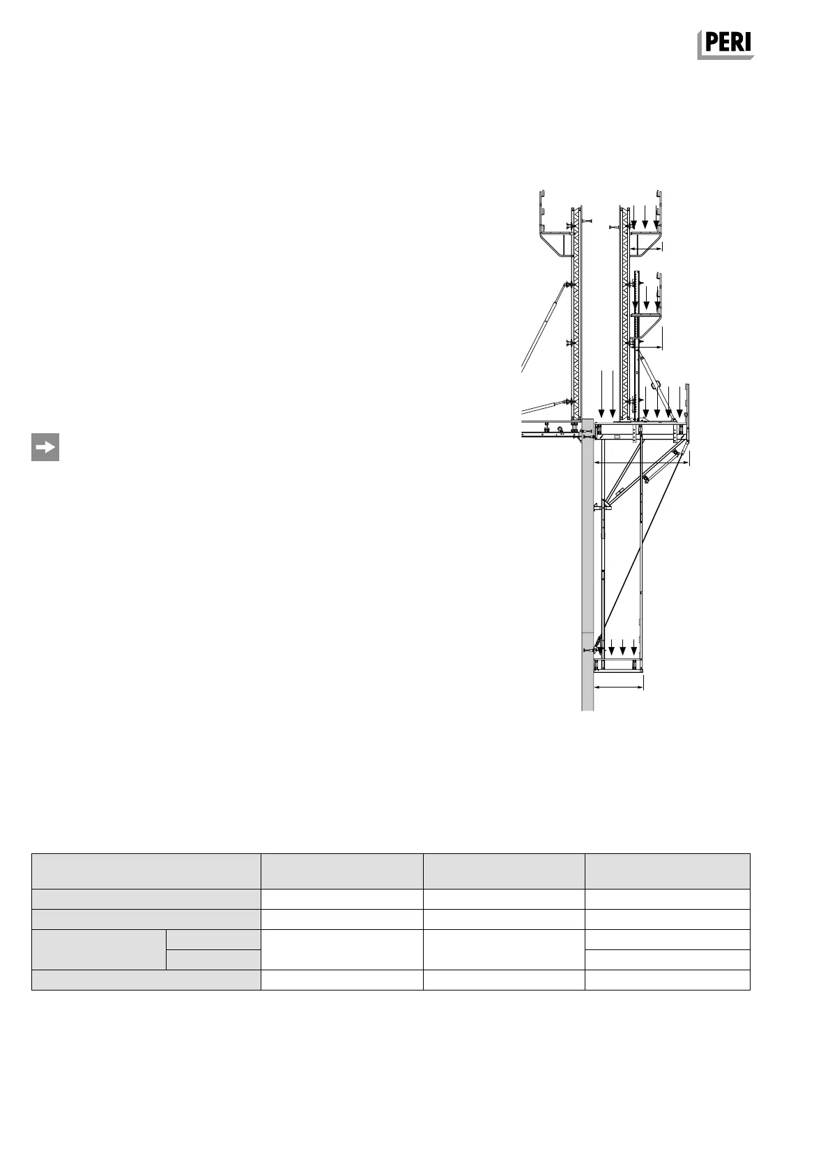
Concreting
platform
Intermediate
platform
Working
platform
Finishing platform
w1
p1
p2
p3
p4
p5
w2
w3
w4
Table 3
Permissible load
* Maximum permissible live load for “Working” operating condition:
– Loads are evenly distributed. One-sided loading of cantilevered platform areas is not permitted.
– If loading several platform levels, only one level can be fully loaded – all other platform levels only up to 50%.
– Storm conditions: reduced load of p
4
= 133 kg/m² on the working platform for material left behind.
Platform Platform width w Dead load of the
platform
Life Load Capacity*
Concreting platform w
1
= 0.71 m 30 kg/m
2
p
1
= 150 kg/m
2
Intermediate platform (if required) w
2
= 0.71 m 30 kg/m
2
p
2
= 150 kg/m
2
Working platform
Wall side
w
3
= 2.40 m 50 kg/m
2
p
3
= 300 kg/m
2
Guardrail side p
4
= 200 kg/m
2
Finishing platform w
4
= 1.15 m 50 kg/m
2
p
5
= 75 kg/m
2
AuV CB 240 EX.indb 56 29.06.16 09:45