27
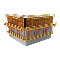
CB 240 Climbing Formwork
Instructions for Assembly and Use – Standard Configuration
B1 Work on the Construction Site
5.2
5.1
5.4
5.5
5.3
5.8
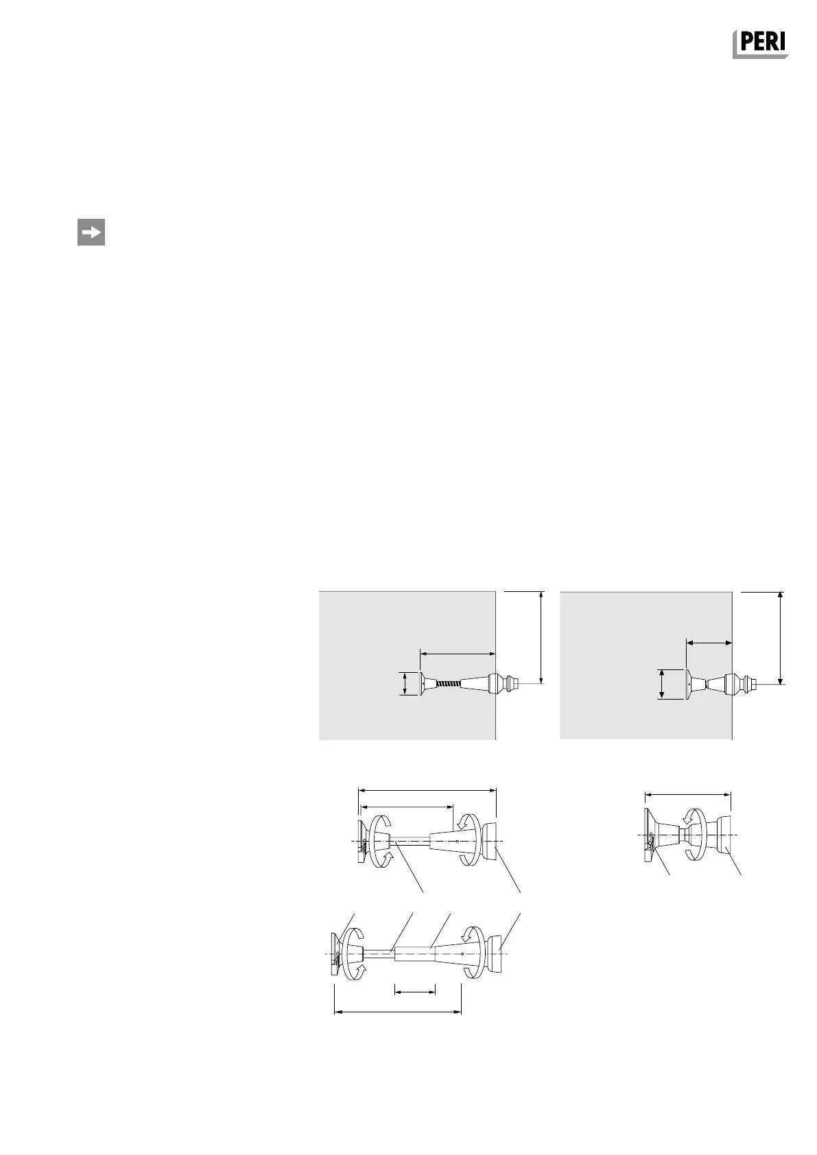
Fig. B1.04
Version 2
Screw-On Cone-2 M24/DW 20
Anchoring depth h = 15.5 cm.
1. Completely insert Screw-On Cone
(5.1) into the Threaded Anchor Plate
DW 20 (5.2). (Fig. B1.05)
Version 1
Climbing Cone-2 M24/DW 15
Anchoring depth h according to static
requirements.
1. Check tie rod length L
1
.
2. Screw in DW 15 Tie Rod into the
climbing cone (5.3).
3. If necessary, pull DR 22 Spacer Tube
(5.8) over the DW 15 Tie Rod (5.5).
4. Completely screw in and tighten
Threaded Anchor Plate DW 15 (5.4) on
the tie rod (5.5). (Fig. B1.04)
Ø 10 cm
h = 15,5 cm
h ≥ 18,5 cm
Ø 8 cm
Anchoring depth h
CB 240 = 45 cm
CB 160 = 35 cm
Anchoring
Preparations for Use
– With different concreting heights, an-
chor spacings with < 5 cm deviations
can be compensated by means of the
height adjusting unit. With larger devi-
ations, more drilled holes are provided.
– During the first installation, compare
the anchor spacing with the bracket
spacing of the pre-assembled platform.
– Dimension and install the leading
anchor according to planning require-
ments.
h = 155 mm
L
1
= h - 80 mm
L
2
= h - 185 mm
L
1
= h - 80 mm
CB 240 = 45 cm
CB 160 = 35 cm
Fig. B1.05
AuV CB 240 EX.indb 27 29.06.16 09:44
 Loading...