63
CB 240 Climbing Formwork
Instructions for Assembly and Use – Standard Configuration
C1 Planning and Work Preparation
10
3.2
3.1
3.2
3.1
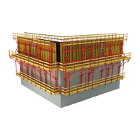
Connecting VARIO GT 24
formwork
Adjustable Brace 164-224
According to the formwork waler spa-
cing, fix the Adjustable Brace (3.1) with
bolts Ø 25 x 180 (3.2) in the bottom hole
(Fig. C1.08.1)
or in the top hole
(Fig. C1.08.2)
of the Strongback.
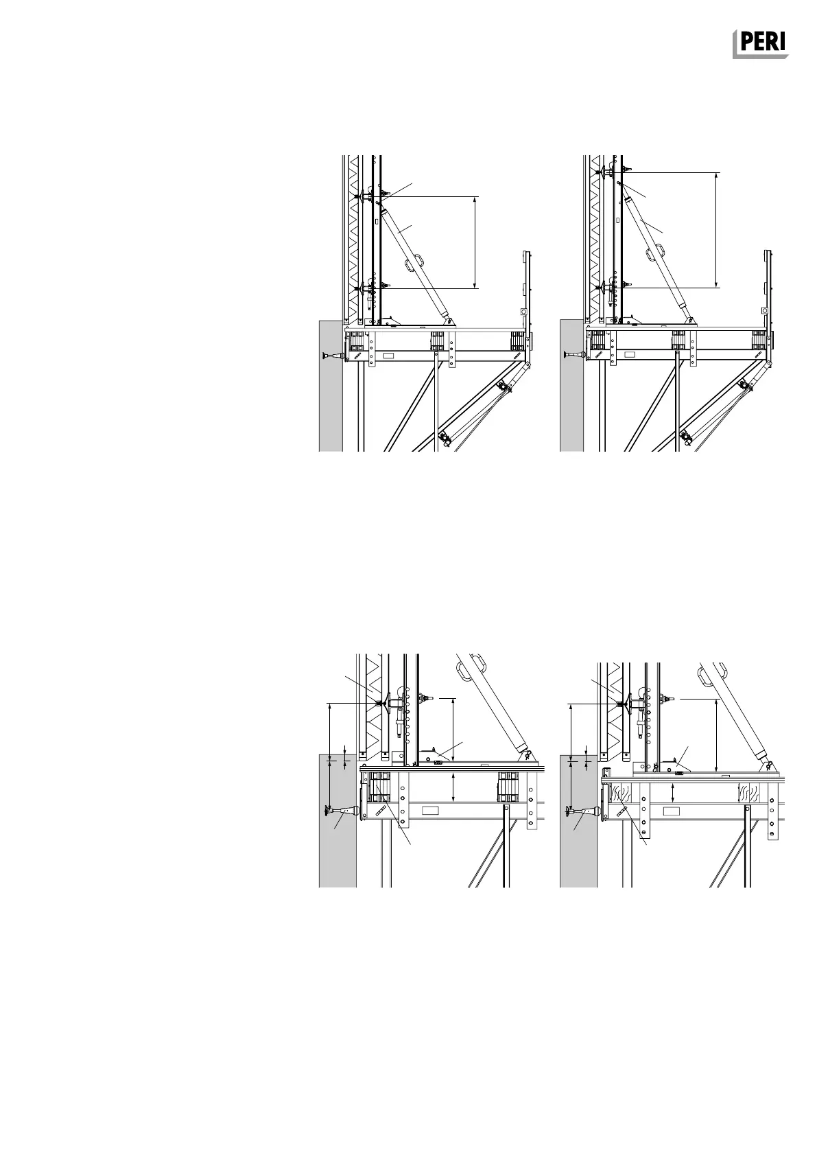
Anchoring
Depending on the height of the girder
(13.1), position the Carriage (2) higher or
lower.
(Fig. C1.09.1 + C1.09.2)
The edge distance of the anchoring (5)
and the positional height of the form-
work (10) remain unchanged.
1,18 m
Fig. C1.08.1 Fig. C1.08.2
1,48 m
45 cm
46 cm
46 cm
51 cm
Fig. C1.09.1
45 cm
16 cm
59 cm
Fig. C1.09.2
5 cm
5 cm
24 cm
13.1
5
10
13.1
5
2
2
AuV CB 240 EX.indb 63 29.06.16 09:46