Advanced Maintenance . 87
WARNING
Be careful, the nearby source housing may be hot.
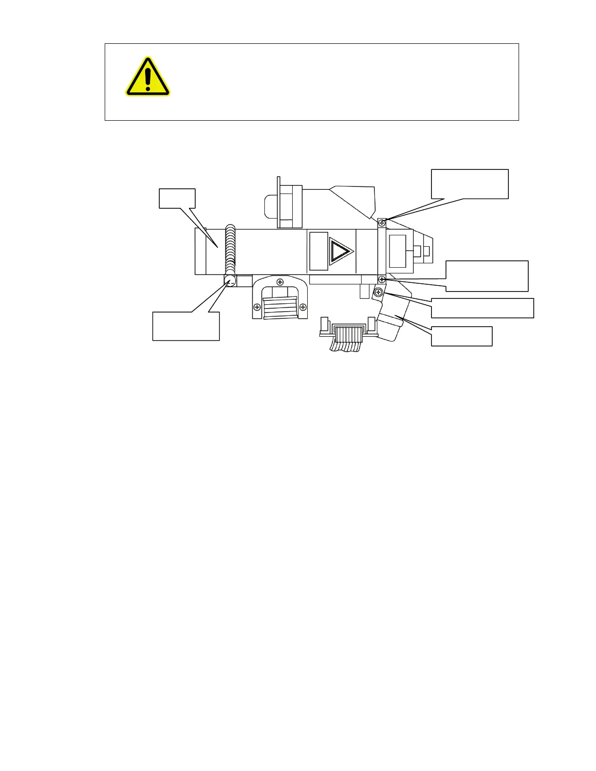
6. Unhook the spring at the rear of the laser, and remove the two screws on the retaining
bracket at the front of the laser (Figure 57).
Figure 57 Laser and power supply installation
7. Remove the laser and power supply; noting the way the cabling is routed.
8. Install the new laser and power supply.
Ensure the laser is pushed fully home to the end stop at the front of the housing.
The laser must be installed so that the yellow laser warning label is facing directly
upwards.
9. Refit the laser retaining bracket and secure with the two securing screws.
10. Secure the spring on the retaining pin.
11. Reconnect the PSU laser cable to the board connector.
12. Secure the laser power supply with the two securing screws (Figure 55).
13. Refit the cable clip (Figure 56), so that it does not get trapped in the cover.
14. Secure the laser cabling to the laser power supply with a new cable tie.
15. Close and secure the main cover.
Refer to page 72, steps 10 to 15.
retaining screw
retaining screw
Laser spring
retaining pin