11
Switchbox Examples
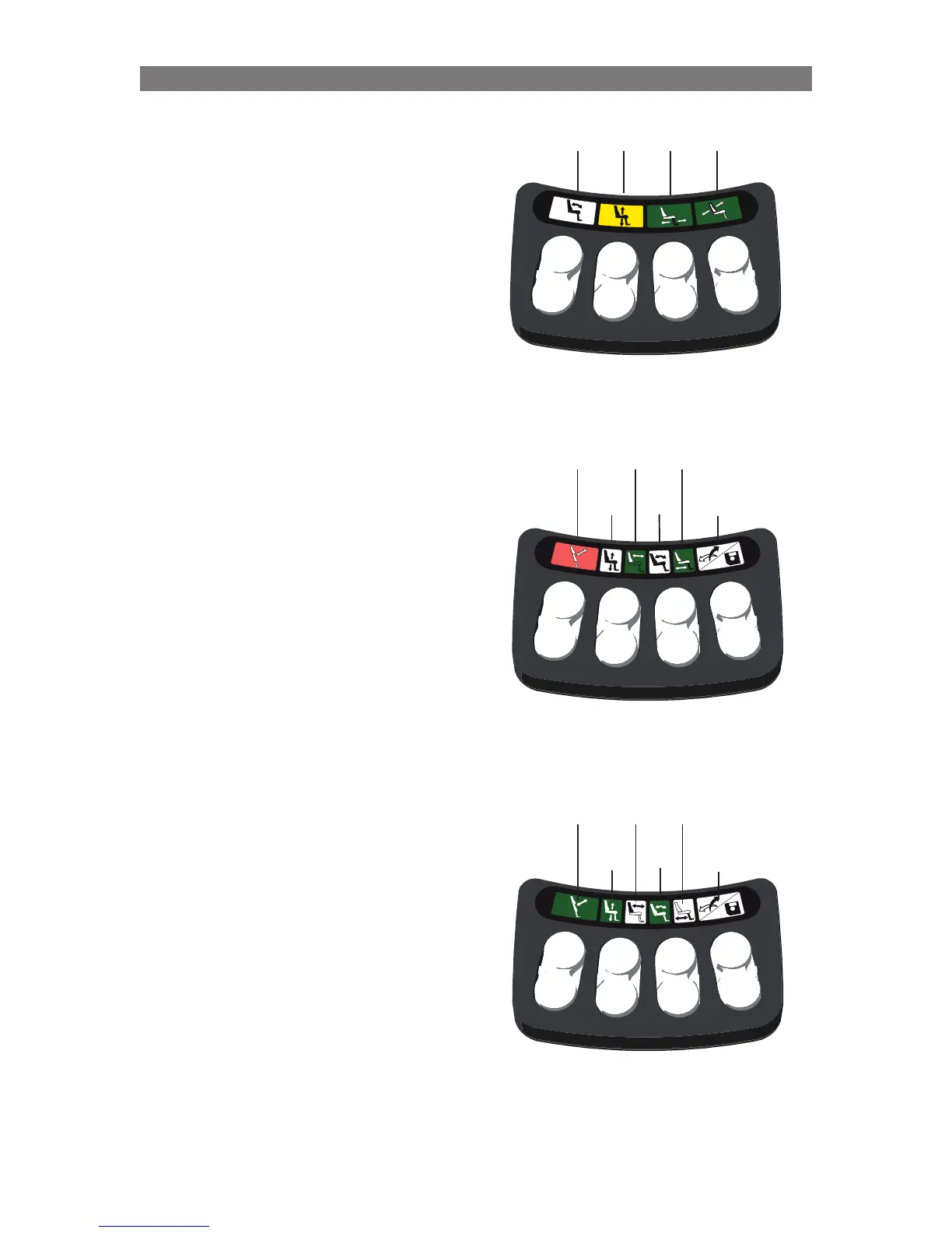
The indications on the switchbox above communi-
cate:
• Switches 2 & 6 will operate the Seat Elevator
• Switches 1 & 5 will not operate a Seat Function
• Switches 3 & 7 will operate the Legrest
(LEDs 1 & 2 are off.)
• Switches 4 & 8 will operate the Backrest
• The Seat Elevator position is limiting the
Chair’s Drive Speed. (LEDs 3 & 4 are solid
yellow.)
The indications on the switchbox above
communicate:
• Switches 1 & 5 will operate Standing
Sequence Switch 4 will “swap” switches 2/6
& 3/7
• Switches 2 & 6 will operate the Backrest
(to enable operation of elevator and tilt)
• Switches 3 & 7 will operate the Legrest
Switch 8 will enter “memory mode”
• The Standing position is preventing the Chair
from Driving (LEDs 1 & 2 are solid red.)
The indications on the switchbox above
communicate:
• Switches 1 & 5 will operate Standing
Sequence Switch 4 will “swap” switches 2/6
& 3/7
• Switches 2 & 6 will operate the Seat Elevator
(to enable operation of backrest and legrest)
• Switches 3 & 7 will operate the Tilt Switch 8
will enter “memory mode”
Solid
Yellow
Solid
Green
Solid
Green
LED
Off
Solid
Green
Solid
Green
LED
Off
Solid
Red
LED
Off
LED
Off
LED
Off
LED
Off
LED
Off
Solid
Green
Solid
Green
Solid
Green
Operation Basic Seat Operation through Switchbox
 Loading...