Mechanical Instructions
EN 12 Q528.1A LA4.
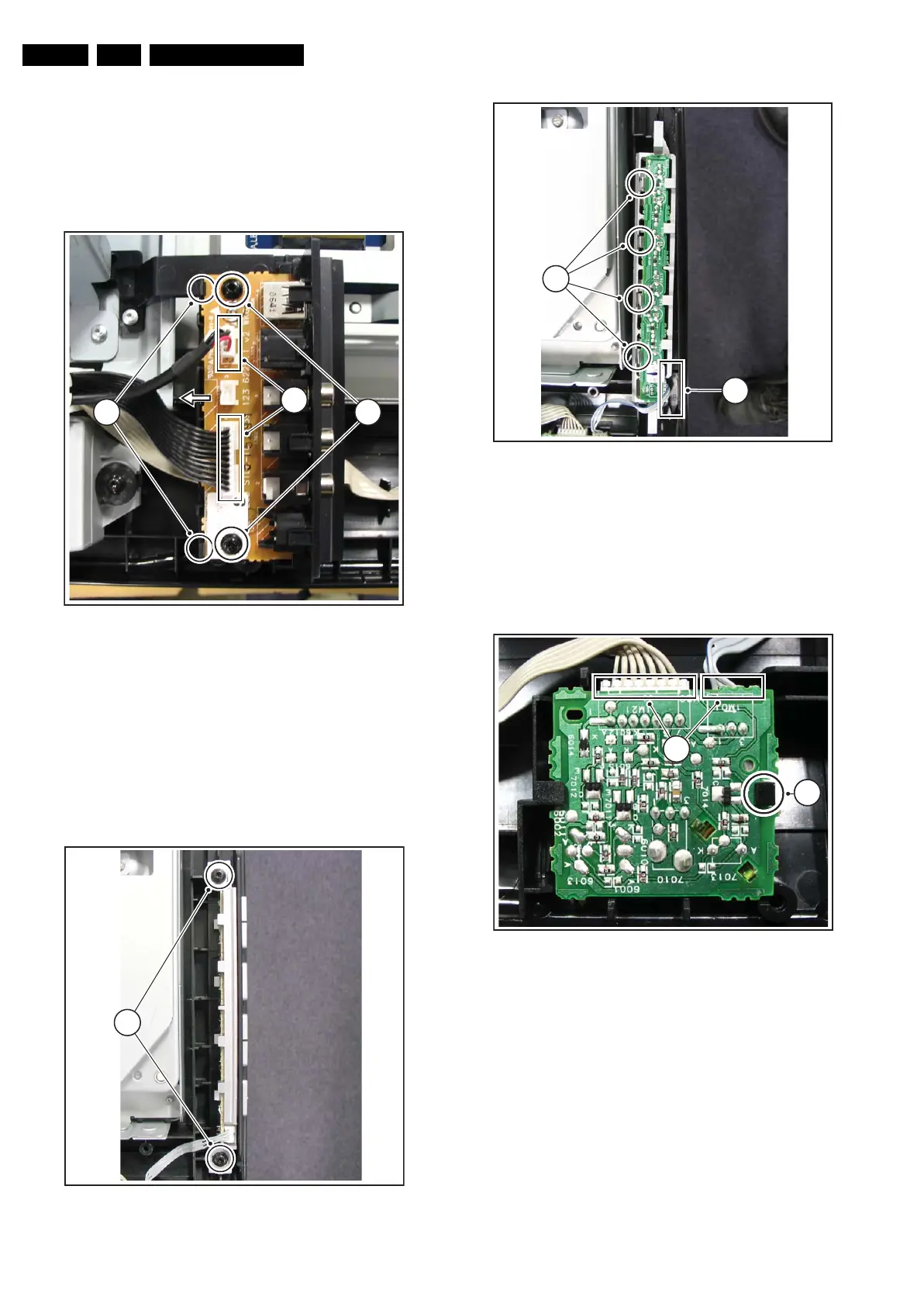
4.3.2 Side I/O Board
Refer to figure “Side I/O Board” for details.
1. Unplug connectors [1].
2. Remove screw [2].
3. Push brackets [3], lift the PWB and slide it to the left out of
its casing.
When defective, replace the whole unit.
Figure 4-10 Side I/O Board
4.3.3 Keyboard Control Board
Refer to figures “Keyboard Control Board -1-” and “Keyboard
Control Board -2-” for details.
1. Remove the screws [1].
2. Lift the clamps [2].
3. Take the PWB out of its casing.
4. Unplug the connector [3] and remove the board.
When defective, replace the whole unit.
Figure 4-11 Keyboard Control Board -1-
Figure 4-12 Keyboard Control Board -2-
4.3.4 IR & LED Board
Refer to figure “IR & LED Board” for details.
1. Release clip [1], lift the board and take it out.
2. Unplug connector [2].
When defective, replace the whole unit.
Figure 4-13 IR & LED Board
4.3.5 Speakers
Refer to figure “Speakers” for details.
1. Unplug connectors [1].
2. Remove screws [2].
H_16770_085.eps
220307
3
1
2
H_16770_086.eps
220307
1
H_16770_087.eps
220307
3
2
H_16770_088.eps
220307
2
1
 Loading...