FL SWITCH 2000
10
PHOENIX CONTACT 107065_en_01
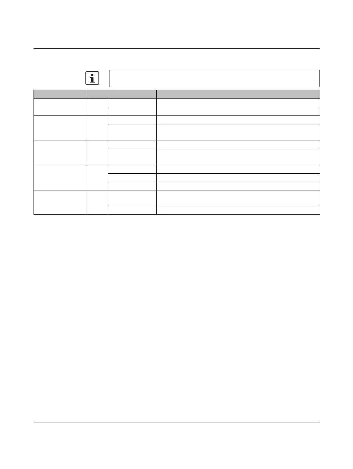
1.1.4 Status and diagnostic indicators
Please note that the meaning of the LEDs differs in Smart mode (see “Using Smart mode”
on page 17).
Des. Color Status Meaning
US1 Green On Supply voltage 1 within the tolerance range
Off Supply voltage 1 too low
US2
(for 2200/2300 ver-
sion only)
Green On Supply voltage 2 within the tolerance range
Off Supply voltage 2 too low
FAIL
(for 2200/2300 ver-
sion only)
Red On Digital alarm output floated, i.e., an error is present
Off Digital alarm output connected to ground potential (ground), i.e., an
error is not present
LNK/ACT
(at port top)
Green On Link active
Flashing Data transmission
Off Link not active
SPD
(at port bottom)
Green/
orange
On Green: 100 Mbps
Orange (for 2100/2300 version only): 1000 Mbps
Off 10 Mbps if Link LED is active