FL SWITCH 2000
12
PHOENIX CONTACT 107065_en_01
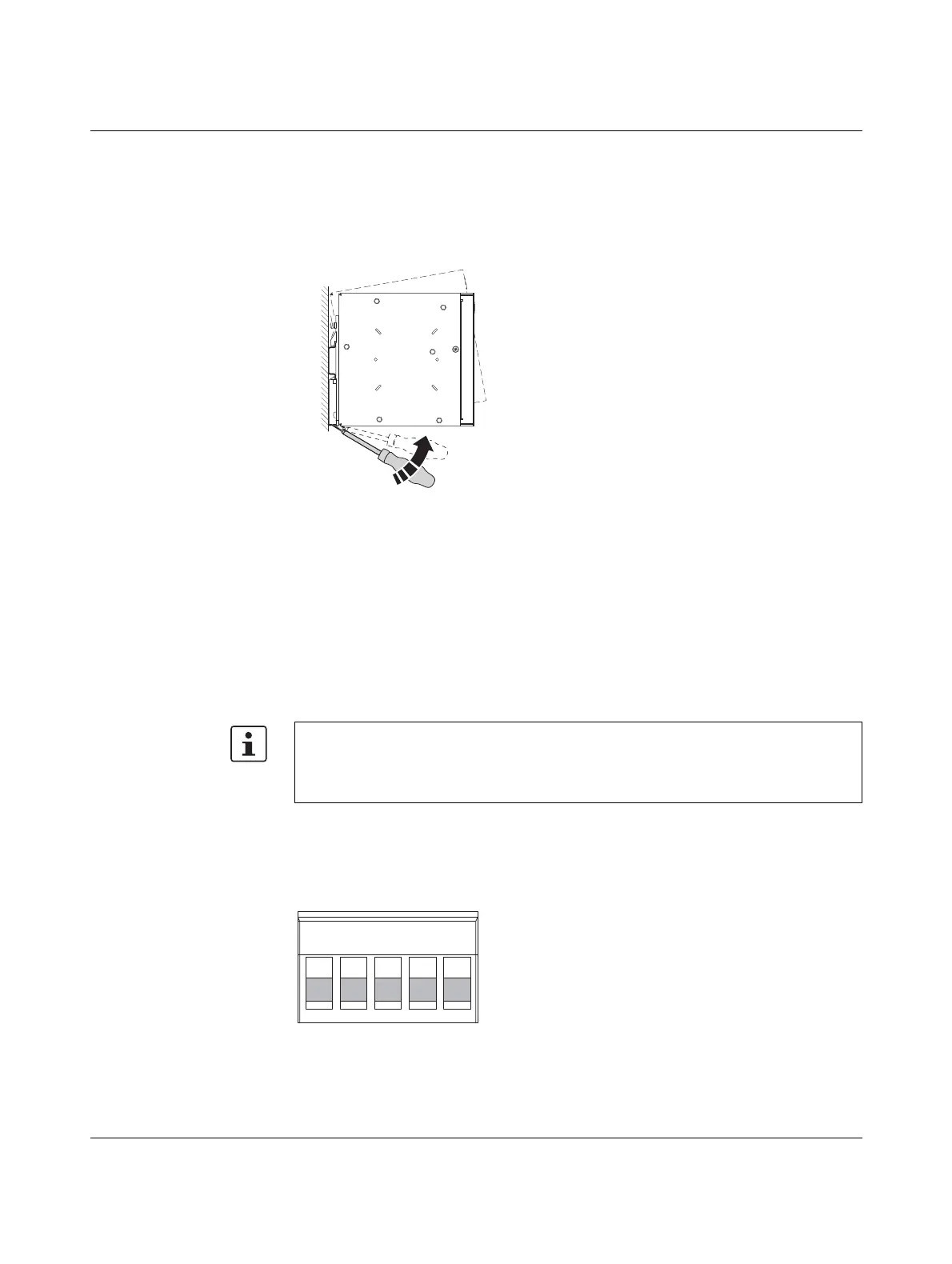
Removal:
• Pull down the positive latch using a suitable tool (e.g., screwdriver). The positive latch
remains snapped out. Then swivel the bottom of the device away from the DIN rail
slightly (B1). Next, lift the device upwards away from the DIN rail (B2).
Figure 2-2 Removing the device
2.2 Installing the devices
2.2.1 Connecting the supply voltage
The device is operated using a 24 V DC voltage, which is applied via COMBICON. For de-
vices in the 2200/2300 version, the voltage can also be supplied redundantly (see
Figure 2-4).
Operation with one power
supply
Figure 2-3 Operating the device with one power supply (example)
For devices in the 2200/2300 version: if redundant power supply monitoring is active (de-
fault setting), an error is indicated if only one voltage is applied. A bridge between US1
and US2 prevents this error message. It is possible to deactivate monitoring in web-based
management or via SNMP.