Mounting and installation
107065_en_01 PHOENIX CONTACT 13
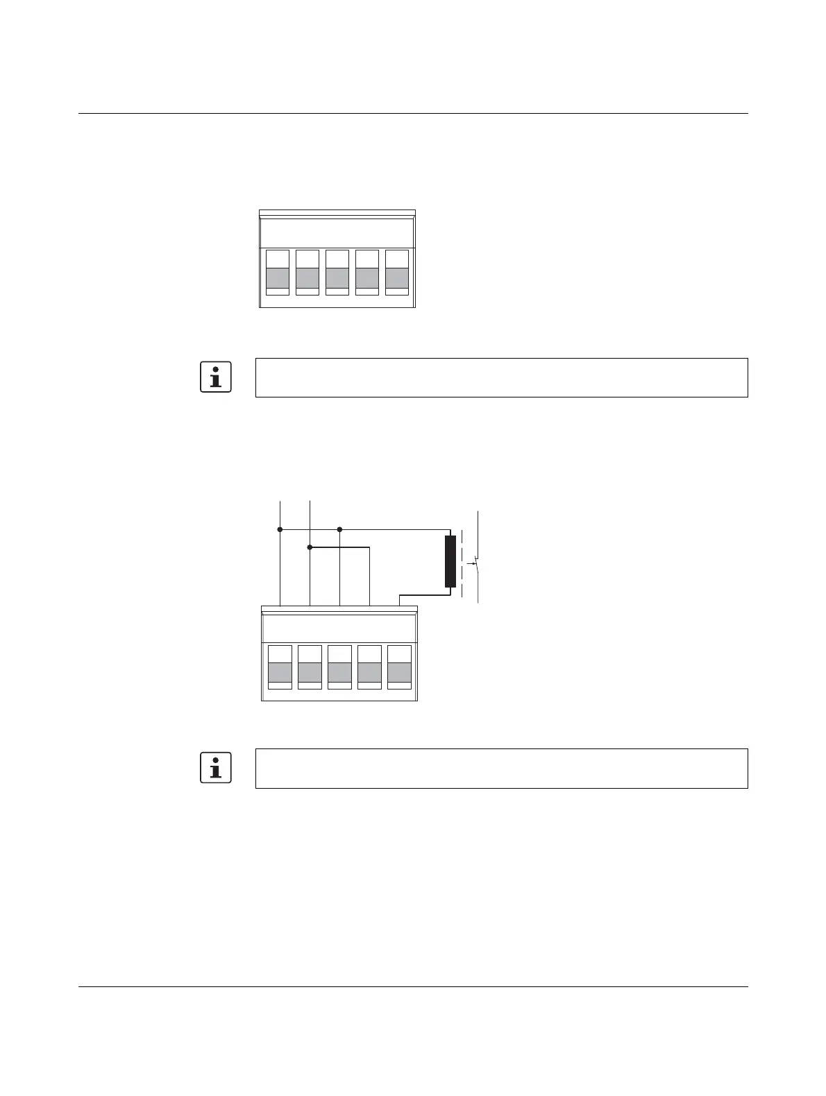
Redundant operation with
two power supplies
Figure 2-4 Redundant operation with two power supplies (example)
2.2.1.1 Connecting a relay to the digital alarm output
The digital alarm output is an open drain output. In normal mode, the output is connected to
ground potential. If an error/alarm is present, the output is floated.
Figure 2-5 Connecting a relay to the digital alarm output
Please note that load distribution does not take place. The power supply unit with the high-
er voltage will supply the device on its own.
Please note that the relay must be suitable for the operating voltage. Use the RIF-0-RPT-
24DC/21 (Order No. 2903370), for example.