Mounting and installation
107065_en_01 PHOENIX CONTACT 11
2 Mounting and installation
2.1 Mounting and removing the devices
Mount the device on a clean DIN rail according to DIN EN 50022 (e.g., NS 35 ... from Phoe-
nix Contact). To avoid contact resistance, only use clean, corrosion-free DIN rails. End
brackets (E/NS 35 N, Order No. 0800886) can be mounted to the right and left of the device
to stop the modules from slipping on the DIN rail.
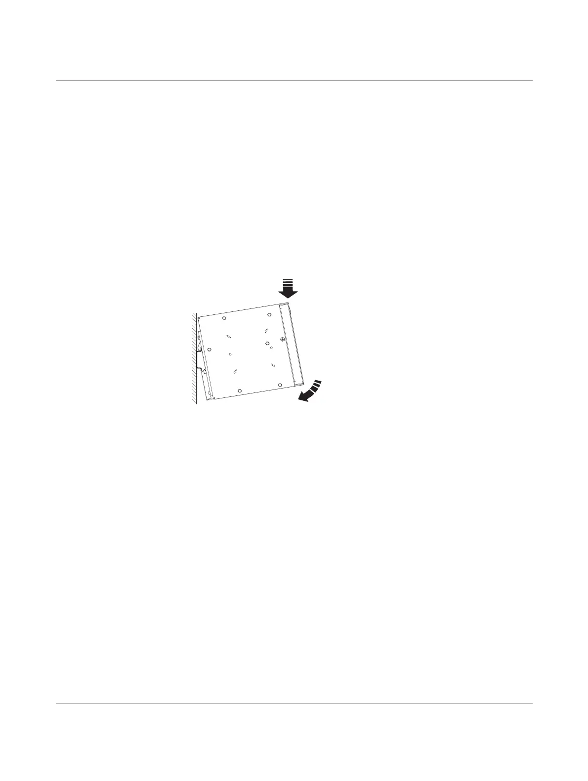
Mounting:
• Place the module onto the DIN rail from above (A1). The upper holding keyway of the
module must be hooked onto the top edge of the DIN rail. Push the module from the
front towards the mounting surface (A2).
Figure 2-1 Snapping the device onto the DIN rail
• Once the module has been snapped on properly, check that it is fixed securely on the
DIN rail.