13
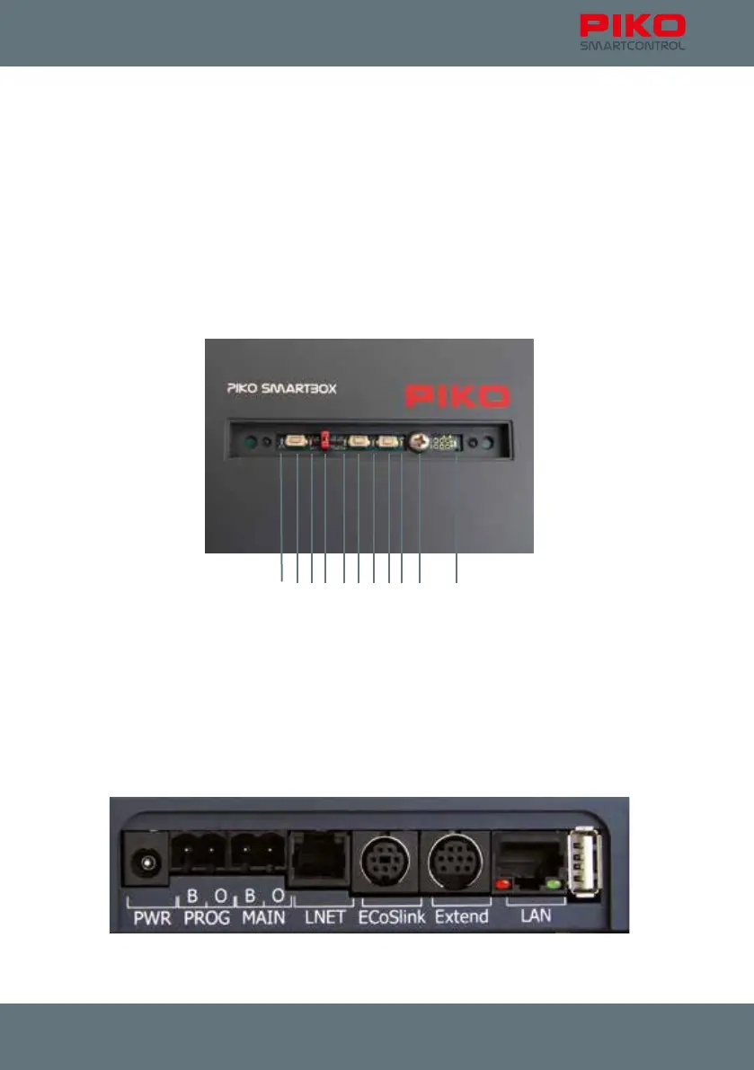
Hardware
top: (each from left to right)
1 status LED for WPS connection
2 button for WPS connection
3 status LED for active connection between PIKO SmartBox and PIKO SmartControl
®
-app
4 jumper (WiFi on/off)
5 status LED for track power
6 button for reset / backup
7 button for reset / backup
8 button for rescue / update
9 status LED for rescue / update
10 crosshead screw for removing upper part of the PIKO SmartBox housing
11 status LED for power status
Backside: (from left to right):
1 5.5 mm socket for power supply
2 track-out for „programming track“
3 track-out for „main track“
4 LNET (Loconet) –socket
5 ECoSlink-socket
6 Extend-socket
7 LAN-socket
8 USB-socket
1 2 3 4 5 6 7 8
111091 2 3 4 5 6 7 8