System
10
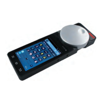
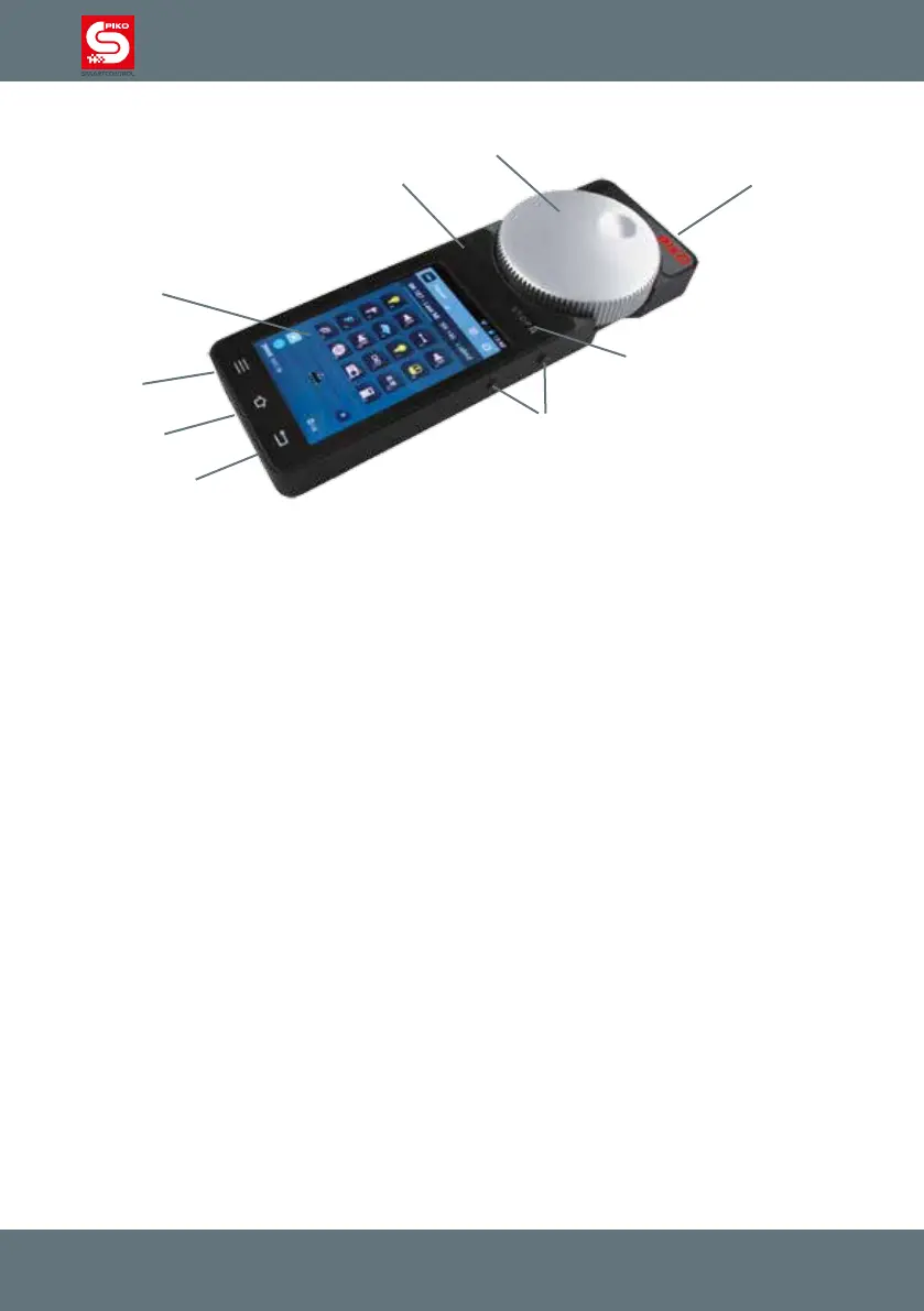
2.2. PIKO SmartController
®
Hardware
1 On / Off switch (top right)
2 Analog controller, motor-powered and with end-switch (top center)
3 Display
4 STOP-button (above display, right side, „Pause“-Symbol)
5 Status-LED (above display left)
6 Four function buttons (right and left side, each 2x)
7 3.5mm stereo headset port (below display left) for headset
8 Mini-USB-port (below display right) for PC connection (update / data) or charging
9 Lanyard-hook (centered below display)
The four function buttons on the sides are programmable, each can be assigned to a specic
function.
For more details about setting up the function buttons see “Getting started”
The motorized analog dial automatically adjusts to the current speed of the loco when setting the
speed on the display, taking over control of a loco or when changing direction.
„Stop / II“-button
The STOP-button is something like a panic switch for the PIKO SmartControl
®
system.
Depending on the delay which is setup in the menu, the button will react immediately or after 0,5
seconds pressing.
Power to the layout will be cut and the status-led switches from green to red. To restart the system just
press the button again.
Please note that the PIKO SmartBox
®
saves all state before the emergency power-off, as soon as you
restart the system all locos will start driving again and switches as well as accessories will keep their
prior position.
The status-led can also switch to red if you choose the option „act as main controller.“ In case the
connection between the PIKO SmartBox
®
and the PIKO SmartControl
®
is lost the system will do an
emergency power-off.
More details can be found under “Getting started”
1
2
3
4
5
6
7
8
9