PIPER AIRCRAFT, INC.
PA-28-161, WARRIOR III
MAINTENANCE MANUAL
PAGE 4
Nov 30/06
1J12
20-00-00
5. Identification of Fluid Line
s
(Refer to Figure 4.)
Aircraft fluid lines are identified by color code markers, words and geometric symbols. The markers
identify each line`s function, content, primary hazard, and the direction of fluid flow.
Most fluid lines are marked with 1 inch tape or decals. Paint is used on lines in the engine induction
system.
Certain lines may also be identified as to the specific function within a system. For example: DRAIN,
VENT, PRESSURE or RETURN.
Lines conveying fuel may be marked FLAM. Lines containing toxic materials are marked TOXIC. Line
containing physically dangerous materials, such as oxygen, nitrogen, or freon, are marked PHDAN.
The aircraft and engine manufacturer is responsible for the original installation of identification markers,
Aircraft maintenance personnel are responsible for their replacement when it becomes necessary.
Tapes, paint, tags and decals are placed on both ends of a line and at least once in each compartment
through which the line runs. Identification markers are also placed immediately adjacent to each valve,
regulator, filter or other accessory within a line.
6. Inspection of Fle
xible Hoses
NO
TE: During the manufacturing process, a condition known as “rubber strike-through” occasionally
occurs. This condition is such that rubber material protrudes through the wire braid cover. This
condition has no effect on hose quality.
It is recommended that flexible hoses be inspected every 100 hours, especially those in the engine
compartments. When inspecting hoses, look for the following conditions:
A. Check each installation to be sure the hose is not kinked, twisted, or distorted. Check for evidence
of abrasion, cuts, and broken wires. Random broken wires are acceptable since wire breaks
sometimes occur during manufacture. Discard hose if two or more broken wires are found per plait
(braid) or more than six broken wires per lineal foot. Broken wires in an area where kinking is
evident is also a cause for rejection.
CAUTION: PUNCTURING THE OUTER COVER OF THE HOSE MAY CAUSE DAMAGE TO THE
HOSE.
B. Check each assembly for deterioration, ply separation of cover or braid, cracks, weather checking,
lack of flexibility, blisters or bulging, collapse, or sharp bending. Blisters on the outer synthetic cover
do not necessarily indicate a faulty hose.
C. Remove hose from assembly if hose shows any visible wear. Inspect hose interior and check for
signs of deterioration, tube collapse, cut rubber, wire braid puncture, or restriction. To inspect hoses
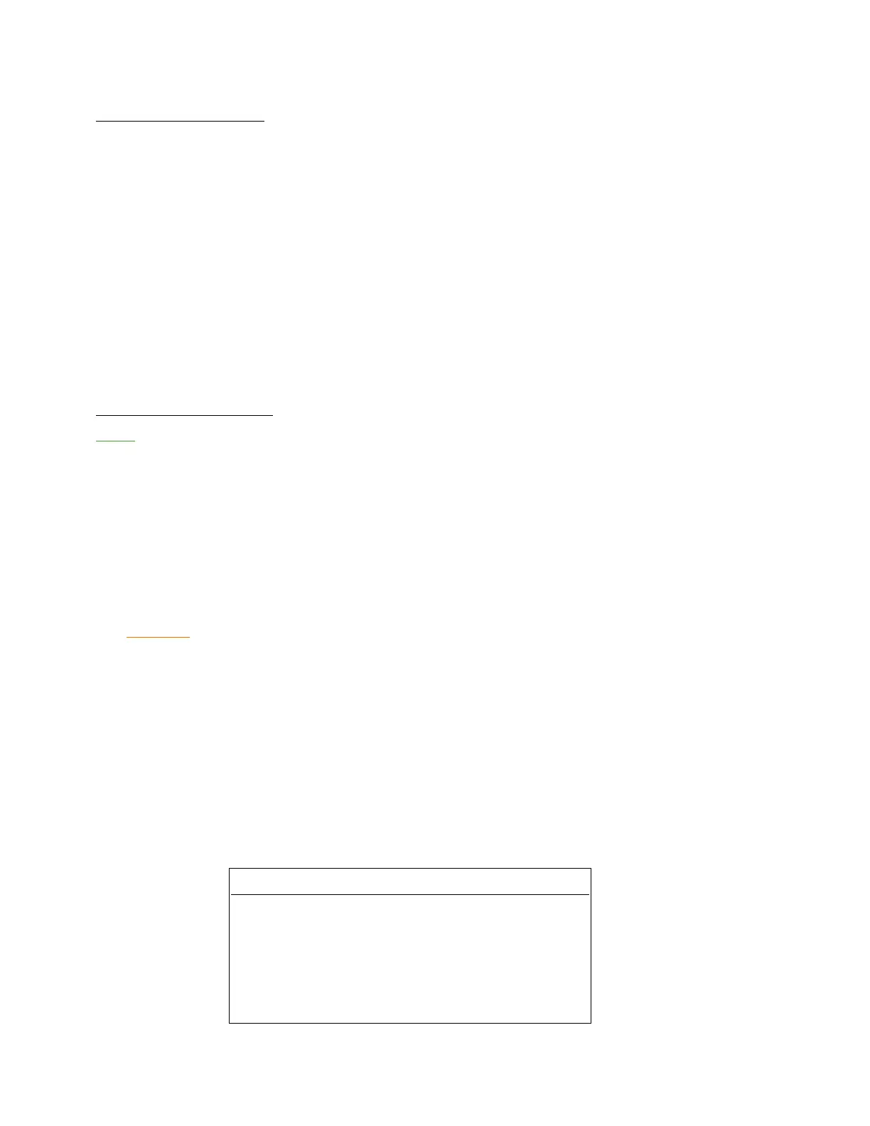
with elbow fittings, use flexible inspection light and viewer, or inspection ball as described in Chart 1
Replace hose if any deterioration exists.
Hose Size Ball Size
- 4 ................................................. 5/64
- 5 ................................................. 9/65
- 6 ................................................ 13/64
- 8 ................................................. 9/32
- 10 ................................................. 3/8
- 12 ................................................. 1/2
- 16 ............................................... 47/64
- 20 ............................................... 61/64
CHART 1
BALL DIAMETERS FOR TESTING HOSE RESTRICTIONS

 Loading...


