PIPER AIRCRAFT, INC.
PA-28-161, WARRIOR III
MAINTENANCE MANUAL
2E3
24-30-00
PAGE 11
Nov 30/06
Voltage 24 Vdc
Rated Output 70 Amperes
(1)
Ground Polarity Negative
Rotation Bi-directional
Rotor (70°F - 80°F)
Current Draw @ 24 Vdc 1.9 - 2.3
Amps
Resistance 10.5 - 12.5
Ohms
Output Test (70°F - 80°F)
Volts 28
Output Amperes 23.0 - 61.0
Min. Alt. Rpm 4000 - 8000
(1)
Useful load 60 amperes, rated load 70 amperes.
CHART 2
ALTERNATOR SERVICE TEST SPECIFICATIONS (ES ALU8421LS)
D. Alternator Test
CAUTION: ALTERNATOR SHOULD NOT BE RUN MORE THAN 2 MINUTES FOR EACH TEST
POINT.
NO
TE: Always refer to the appropriate alternator and starter schematic wiring diagram when
installing or testing the alternator.
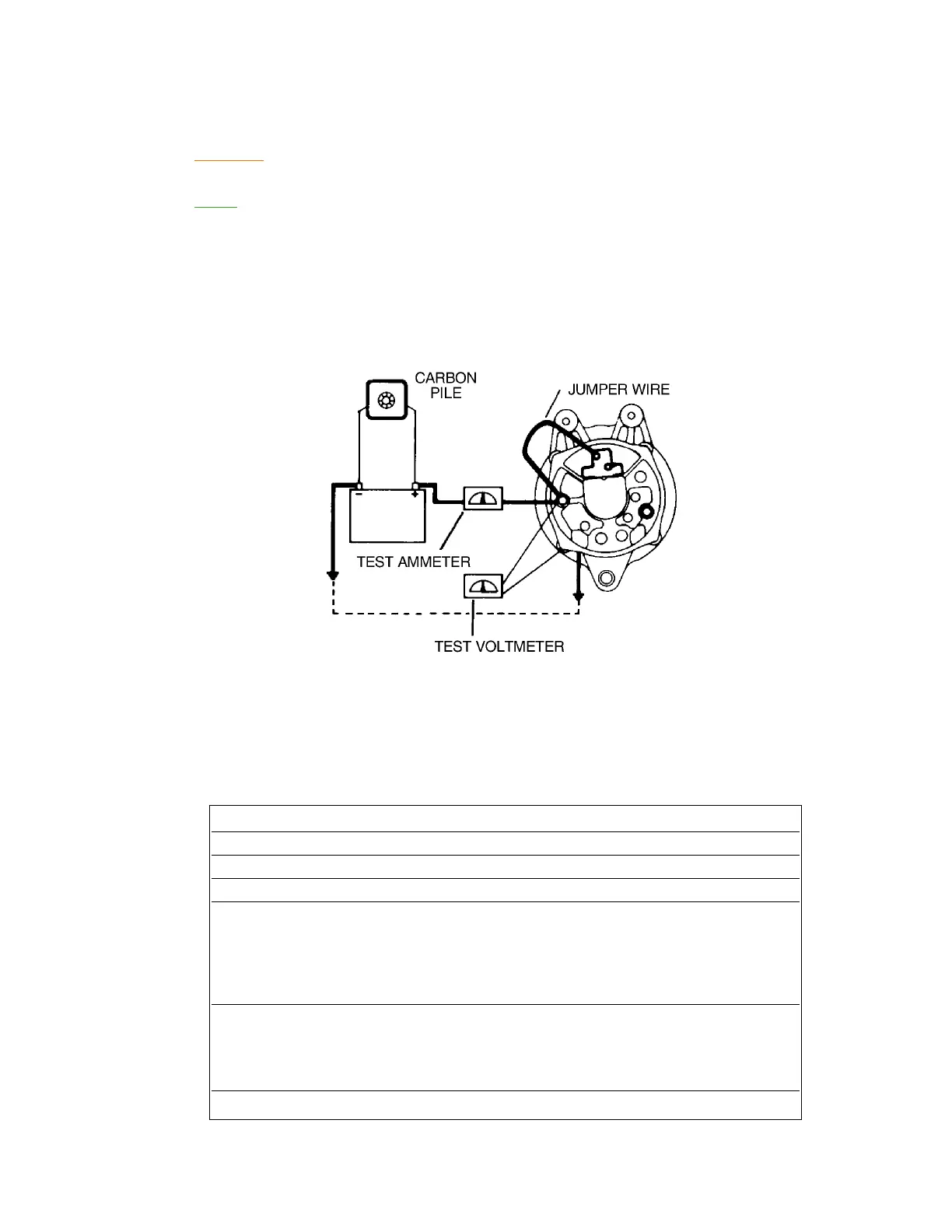
(1) Wiring connections for bench testing the alternator are shown in Figure 3. Refer to Chart 2 for
output test figures. Adjust the carbon pile if necessary, to obtain the specified voltage.
(2) After bench testing the alternator, install the safety wire and install the alternator on the engine.
Testing Alternator
Figure 3

 Loading...


