5.2 Connecting mains cable
A
bout this task
WARNING
Ensure that the mains leads are not connected to any power source before
connecting them to the unit.
NOTE
Do not peel the protective sleeve of the mains power cable more than
necessary to keep the leads of the cable as short as possible. The maximum
length of the peeled line and neutral leads is 30 mm.
Steps
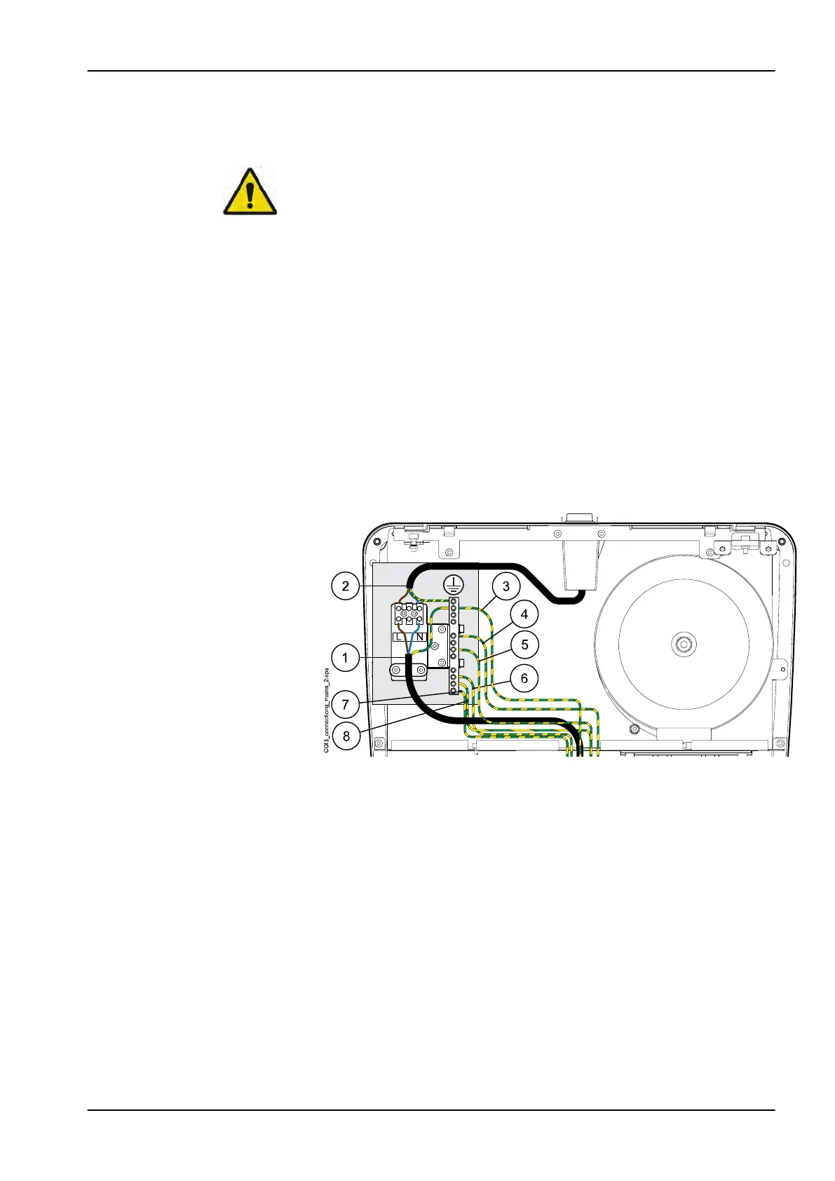
1. Route the mains cable that comes from the floor to the mains terminal.
2. Connect the line lead of the cable to the terminal marked L. Connect the
neutral lead of the power supply cable to the terminal marked N on the
terminal block (1). The on/off switch is connected to the terminal block at
the factory (2).
3. Attach the grounding lead to the ground terminal.
4. These grounging leads are connected to the junction box ground
terminal during the installation: Emerald (optional) (3), chair seat (4),
chair front ground panel (5), junction box cover (6), seat bottom gound
point (7) and OP delivery arm console (8).
5.
Place the Main control PCB back to its position.
5.3 Connecting chair cables
About this task
The chair cables must be connected before the chair can be driven out from
the transportation position.
Steps
1. Do not remove the jumper from the connector P5 on the Main control
PCB yet.
5 Installing junction box
Installation manual Planmeca Compact i3 19