Chapter G - COLUMN
G-36 ProMax X-ray unit with Dimax3
REPLACING PCBS
Technical Manual
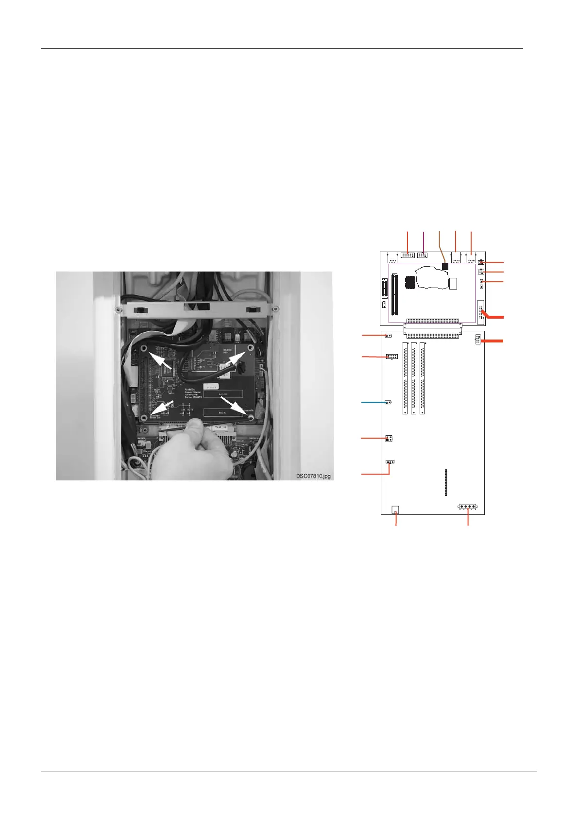
6.2 ETHERNET PCB and CPU PCB
Remove the front cover plate according to the instructions given in section 2.1 “Removing the
telescopic column upper front panel” on page G-9.
Disconnect all the cables that are connected to the Ethernet PCB and CPU PCB.
Detach the Ethernet PCB from the screws on every edge from the CPU PCB.
In case you are replacing the CPU PCB, unscrew the CPU PCB attachment screws with the
2.5mm Allen key and detach the CPU PCB from the Power PCB. Remove the CPU PCB.
Install the new PCB in reverse order. Note, that all the cable connectors are labeled.
Figure 43
J12
J13
J12
J13
J11
J10
J9
J10
J9
J8
J2
J1
121-10-02
Powe r P C B
J3
J5
J4
J6
J10
J11
J8
J12
J7
J3
J1
J1
J1
J
J3
J2
J13
J14
J1
J15
121-10-03
CPU PCB
PSU
J7
J8
J2
J7
J3
PLANMECA
Promax Ethernet
121-10-25
Rem_ethernet_1.eps

 Loading...


