Chapter D - PREVENTIVE MAINTENANCE
ProMax X-ray unit with Dimax3 D-5
MECHANICAL CHECKS
Technical Manual
3 MECHANICAL CHECKS
3.1 Column motor nut
The column motor is equipped with double motor nut assembly consisting of lower, solid nut
(primary), and upper, floating nut (secondary). In case the primary nut fails, the secondary nut
becomes active. The visual check of the column motor nut assembly must be performed once
a year as follows.
Switch the unit off. Remove the two rear cover plates of the telescopic column as described in
section 2.2 “Removing the telescopic column rear cover plates” on page G-11. Switch the unit
off.
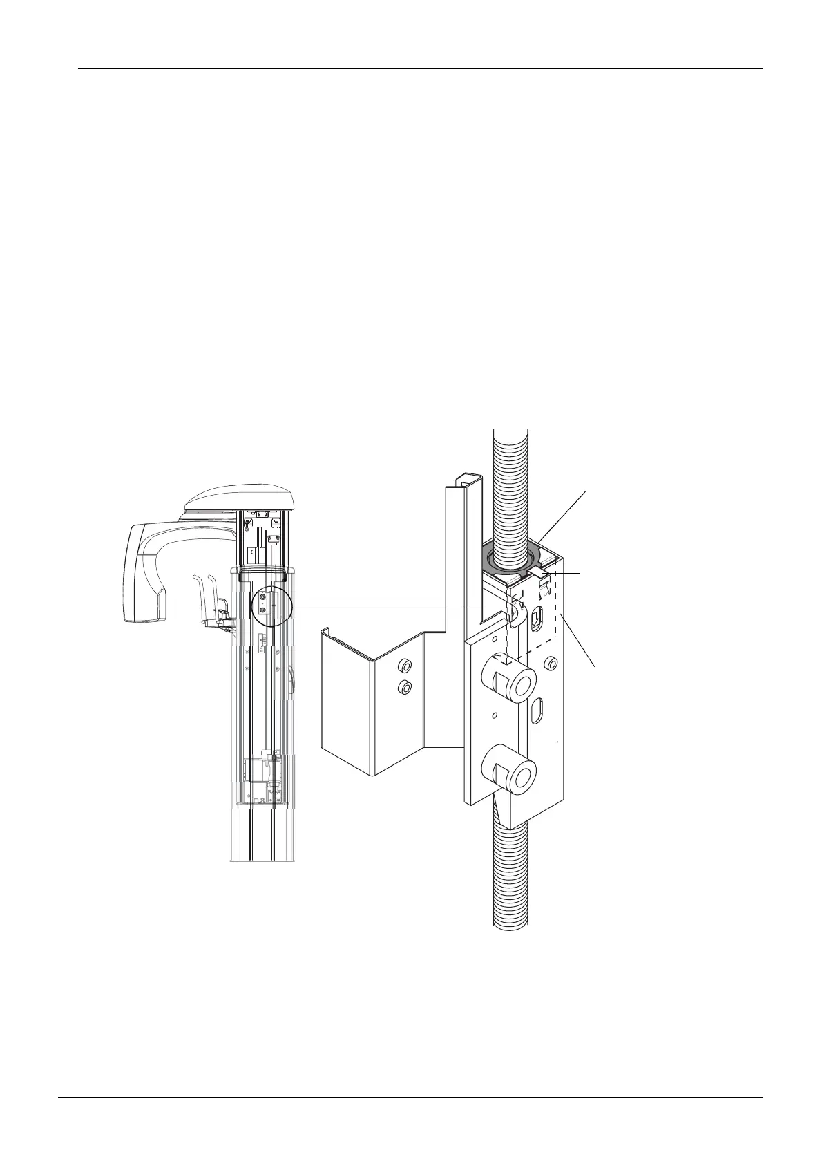
The column motor nut assembly is attached to the stationary column and can be seen from
the opening on the stationary column top. Check, whether the lug of the indicator sheet is
bent and the top surface of the secondary motor nut is level with the edge of the column nut
frame, or a little higher (see Fig. 1 below).
Figure 1
In case the secondary nut is clearly inside the column nut frame and the lug of the indicator
sheet is straightened, the column motor nut assembly must be replaced according to the
instructions given in section 3.2 “Replacing the lift nut assembly” on page G-19.
Liftnut2.eps
Column nut frame
Upper motor nut
Lug of the indicator sheet

 Loading...


