Chapter H - CEPHALOSTAT
H-62 ProMax X-ray unit with DImax3
REMOVING THE HOUSINGS AND COVERS
Technical manual
4 REMOVING THE HOUSINGS AND COVERS
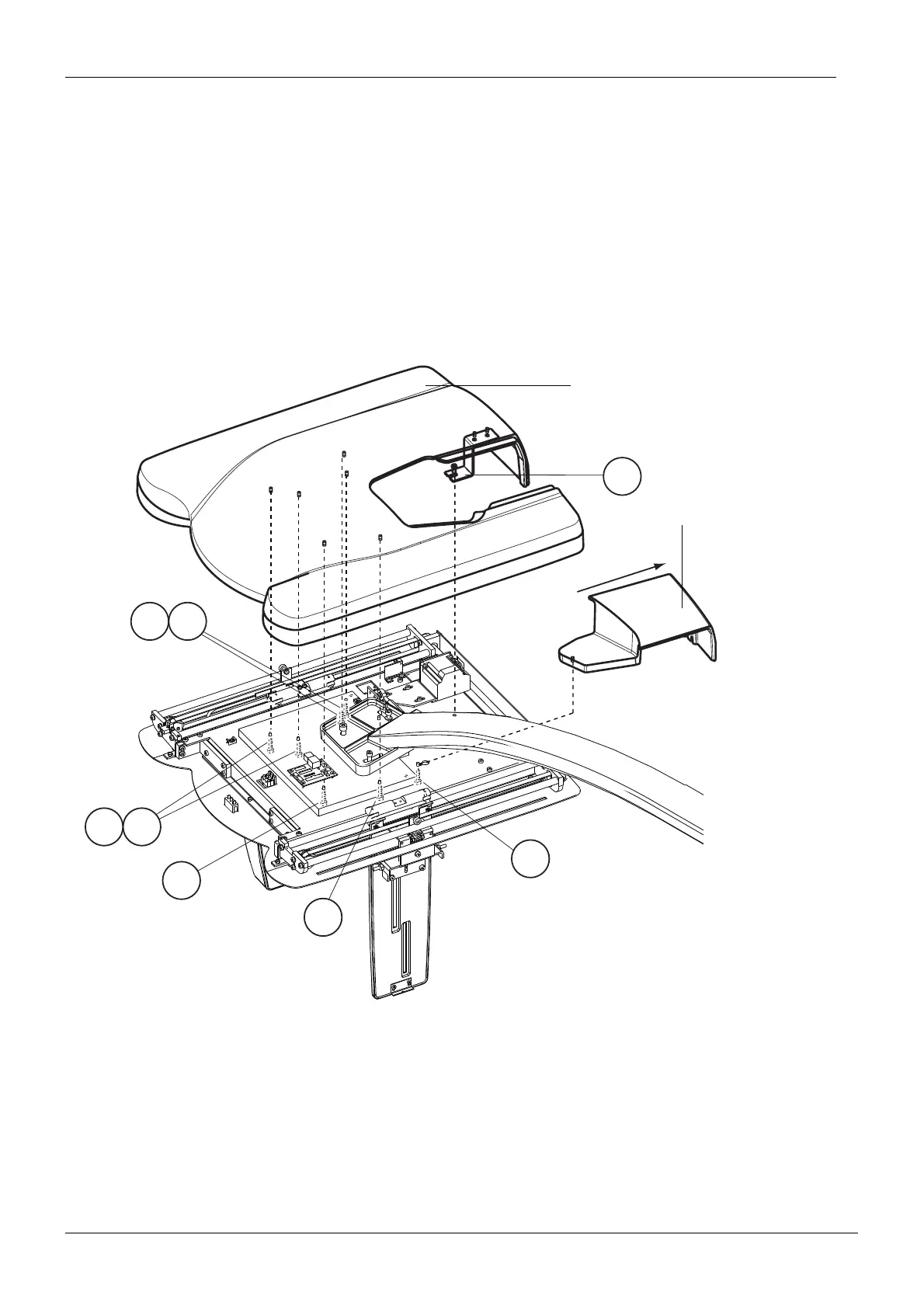
4.1 Removing the housings of the head support
The screws of cephalostat housings can be reached through the ear post holder attachment
opening on the rotatable head support cover. Note that you have to rotate the rotatable head
support to different positions to reach all the attachment screws. The back housing is
attached with one M5x10 DIN 7984 screw (Fig. 110, 1), and the large front housing is
attached to the head support with seven M5x10 DIN 7984 screws (Fig. 110, 2 - 8).
Figure 110 Removing the ceph head support housings.
1
8
PXR_Adj_digiceph27.eps
54
76
3
2
Front housing
Back housing

 Loading...


